background image

SERVICE 

ADJUSTING HIGH VOLTAGE OUTPUT


In case of excessive  arcing on  a clean,  dry cell, there is 
an adjustable resistor mounted on the power board. 

1.  Turn off the system switch before opening the unit.  

2.  Remove  the  cover  by  slipping  the  „S‟  hook  from  the 

chain and letting the cover gently down. 

3.  Lift the cover up off the rear hinge. 

4.  Remove the power box cover. 

5.  With  a  small  slot  screwdriver,  adjust  “R-2”  slightly  to 

reduce voltage to the cell.  Do not reduce the voltage 
too  much  or  the  efficiency  of  the  Air  Cleaner  will  be 
reduced. 

 
REMOVING THE POWER BOX 

1.  Shut off main breaker or switch. 

2.  Remove the cover as described previously. 

3.  Open power box cover. 

4.  Disconnect the following wires: 

Terminal Block   - Red, blue, black and white  

  leads from motor 

- Supply line leads 

Power Board 

 - Orange leads on HV1 and HV2 

Remove  the  two  nuts  holding  the  power  box  to  the  cell 

section.


TROUBLESHOOTING GUIDE


PROBLEM 

CHECK 

Unit Does Not 
Operate 

1.  Main breaker is 

ON

 or voltage is 

supplied to unit. 


2.  Main  supply  fuse  or  breaker  is 

not tripped. 


3.  Unit  cover  is  completely  closed 

and locked into place. 


4.  System switch is 

ON

Performance 
Indicator Light 

OFF 

1.  System switch is 

ON


2.  Remove  cell,  close  access  door 

a n d  t ur n   u ni t  

O N

.    I f 

Performance  Indicator  is still off, 
problem is in the power box.   If 
light comes on with no cell, then 
there is a short circuit in the cell.  
Look  for  bent  plates,  broken 
ionizing wires or burnt insulators.  
Ensure  cell  is  completely  dry 
after washing. 

Performance 
Indicator Light 

ON

1.  Fan  control  switch  is  in  proper 

position. 


2.  Motor  leads  are  connected  to 

terminal block. 

Cell Arcing 
Excessively 

1.  Cell  is  completely  dry  after 

washing. 


2.  Cell  plates  are  not  bent  or 

spaced too close. 


3.  Cell  insulators  are  not  cracked, 

broken or burnt. 


4.  Cell is dirty and needs cleaning. 


5.  Broken ionizing wires. 

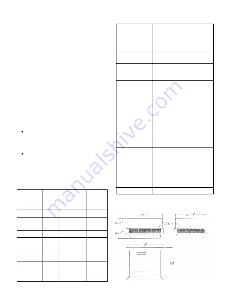
Dimensions 

Length 

24 in 

61.0 cm 


Width 

28 in 

71.0 cm 


Height 

15 in 

38.1 cm 

Weight 


70.0 lbs 

32.0 kg 

Input Voltage 


120 V        60 Hz 


220 V        60 Hz 


220-240 V 50 Hz 


Power 
Consumption 
(maximum) 


150 Watts 


Air Flow 

Hi 

712  CFM 

1210 m

3

/hr 


Medium 

575  CFM 

  977 m

3

/hr 


Low 

440  CFM 

  748 m

3

/hr 

Motor 


1/33 HP 


Summary of Contents for SSC-7

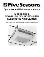
Page 1: ...Operation And Maintenance Manual MODEL SSC 7 SEMI FLUSH CEILING MOUNTED ELECTRONIC AIR CLEANER IMPORTANT PLEASE READ MANUAL BEFORE OPERATING UNIT ...

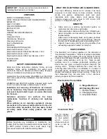
Page 2: ...gi bacteria viruses and more down to 0 01 micron 0 01 micron 1 2 540 000 of an inch BENEFITS Helps clear up a smokey environment quickly so customers can dine more comfortably Helps employees reduce suffering from irritated eyes nasal congestion and respiratory problems that lead to absenteeism Helps prevent damaging black and greasy particles from staining ceilings walls and furnishings reducing ...

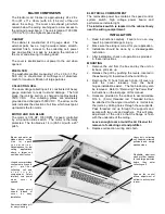
Page 3: ...e ionizing section is charged at approximately 7500 VDC The collecting plates are alternately grounded and charged at 5000 VDC The arrow on the cells indicates the direction of air flow which must point up towards the fan motor MOTOR AND FAN BLADE The motor is 1 33 HP 1050 RPM 3 speed controlled by a 3 position slide switch The motor is thermally protected The fan blade is 14 in 35 5 cm with a 20o...

Page 4: ...ell well with hot water 120ºF 49ºC maximum 5 If dirt or nicotine remains on plates let cell soak in hot soapy water for 30 minutes Never use any instrument to clean the cell as this may damage the ionizing wires or misalign cell plates 6 Spray prefilter with DAX Detergent and rinse well 7 To dry cell tilt on 45º angle against wall with arrow pointing sideways Allow to dry completely for at least 8...

Page 5: ...ker is ON or voltage is supplied to unit 2 Main supply fuse or breaker is not tripped 3 Unit cover is completely closed and locked into place 4 System switch is ON Performance Indicator Light OFF 1 System switch is ON 2 Remove cell close access door and turn unit ON If Performance Indicator is still off problem is in the power box If light comes on with no cell then there is a short circuit in the...

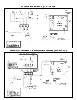
Page 6: ...Electrical Schematic A 120 Volt Electrical Schematic B with Wireless Remote 120 Volt ...

Page 7: ...Electrical Schematic A 220 240 Volt Electrical Schematic B with Wireless Remote 220 240 Volt ...

Page 8: ...a consequence of any misapplication negligent handling improper servicing unauthorized alteration or improper operations 4 Failure to start due to voltage conditions blown fuses open circuit breakers or other damages due to the inadequacy or interruption of electrical service 5 Damage as a result of floods winds fires lightning accidents corrosive atmosphere or other conditions beyond the control ...

Reviews: