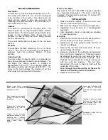
MAJOR COMPONENTS
Description
The Electronic Air Cleaner is approximately 29½ x 27 x
14½ inches (75 x 68.6 x 37 cm). The unit is designed
to be mounted to the ceiling. The steel cover and
intake grill are hinged to allow easy access to the
Collecting Cells and Power Box. The unit is rated up to
1300 CFM (2210 m
3
/hr).
Cabinet
The cabinet is constructed of 20 gauge steel. The
external parts have a tough powder-coated, scratch-
resistant finish. The internal parts are galvanized steel.
Access to the Collecting Cells, Power Box and
Prefilters is made by lifting the cover, sliding towards
the front and lowering.
The cover is interlocked to cut power to the unit when
opened.
Prefilters
The washable Prefilters measuring 12½ x 20 inches
(31.75 x 50.8 cm) are constructed of multi-layers of
aluminum mesh for maximum filtration of large
particles.
Collecting Cells
The dual voltage Collecting Cells are constructed of
heavy gauge aluminum to resist rust and damage. The
first stage, the ionizing section, is charged at
approximately 7500 VDC. The collecting plates are
alternately grounded and charged at 5000 VDC. The
arrow on the Cell indicates the direction of air flow
which must point up towards the fan motor.
Motor & Fan Blade
The motor is 1/12 HP, 1050 RPM, 3 speed, controlled
by a 3-position slide switch. The motor is thermally
protected. The fan blade is aluminum, 18 inches (45.7
cm) with a 16˚ pitch.
INSTALLATION
1. Read instructions carefully. Failure to do so may
result in product damage or injury.
2. Make sure the sizing is correct for your application.
3. Installation should be done by a knowledgeable
technician.
4. After installation, check out operation as provided
in these instructions.
Mounting
1. Remove the unit from the box with packing still on
the unit and lay it on its back, grill side up.
2. Release the cover by sliding towards the front of
the unit and lifting up.
3. Remove the "S" hook from each chain, tilt cover
up, and release from back.
4. Holes are provided in the cabinet to accommodate
5/16 inch (8 mm) threaded rod. Threaded rod can
be attached to angle iron, laid across the joists,
and drilling holes through these supports. Pass
threaded rod up through the supports and secure
with two nuts and washers. This will allow
adjustment of the unit so that it is flush with the
underside of the ceiling.
Leave enough room around the Air Cleaner for
removal of Collecting Cells and Prefilters.
5. Replace cover and chain.
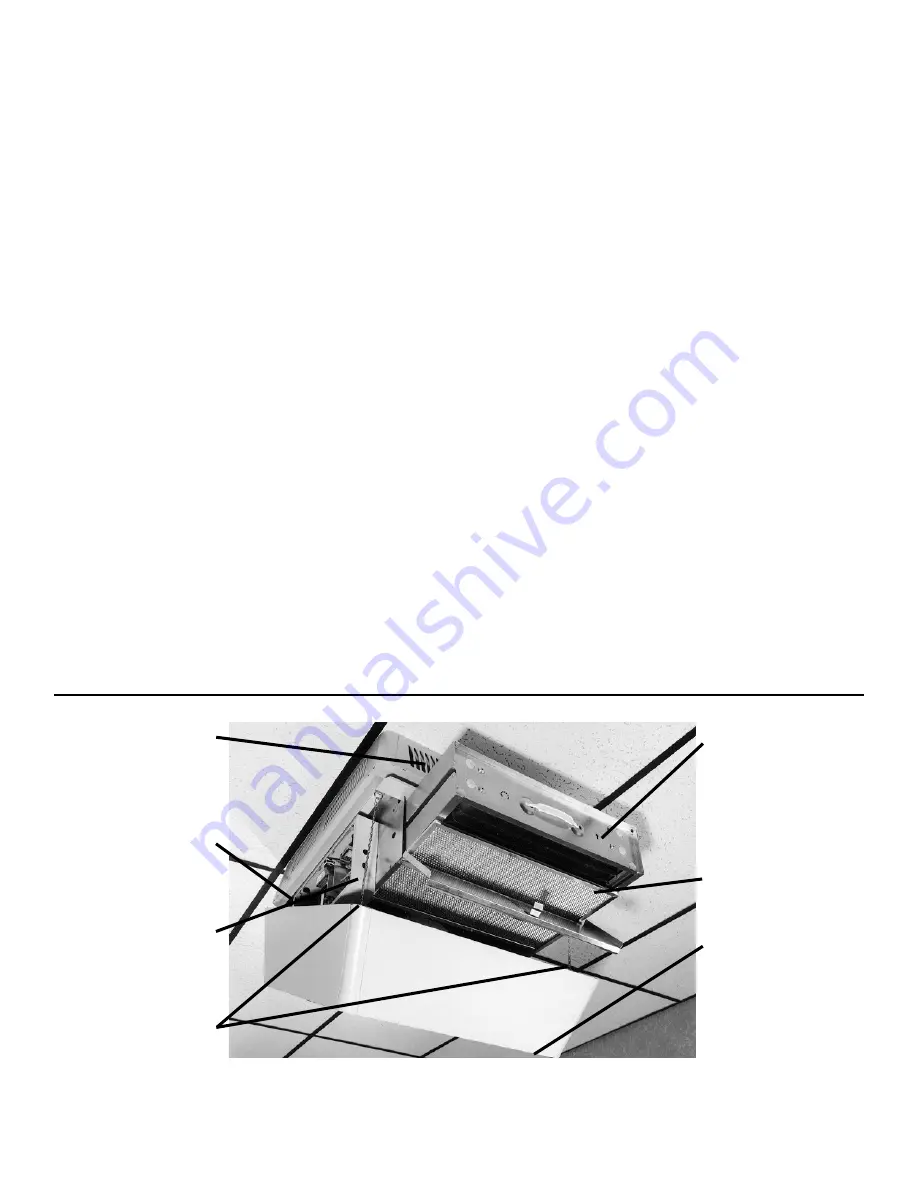
Blower and Motor are
hidden behind 4 directional
discharge air grills.
Rear Hinges permit smooth
release of cover for easy
installation.
3-Speed Fan Control allows
adjustment of air flow to
activity level in room.
Hinged Cover provides
convenient access to Grill,
Prefilters and Collecting
Cells. Safety interlock cuts
power when cover is
opened.
Heavy duty Collecting Cells
(2) capture airborne
pollutants and simply wash
clean.
Washable, aluminum mesh
Prefilters (2) catch lint and
large particles before they
enter collecting cells.
Removable Intake Grill for
easy cleaning.


