12 / 28
FMod-IPECMOT 48/10 User Manual v2.5
TX3-
Negative LVDS differential data input
17
TX3+
Positive LVDS differential data input
18
BL EN
Backlight enable
21
PWM
Backlight Dimming
22
12V BL
Screen backlight power supply
23, 24
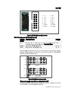
The five differentials pairs must be twisted on the cable.
If the screen has only an 18bits color depth, the pair TX3 must not be
connected.
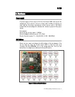
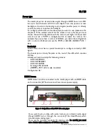
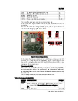
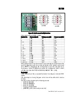
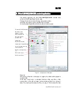
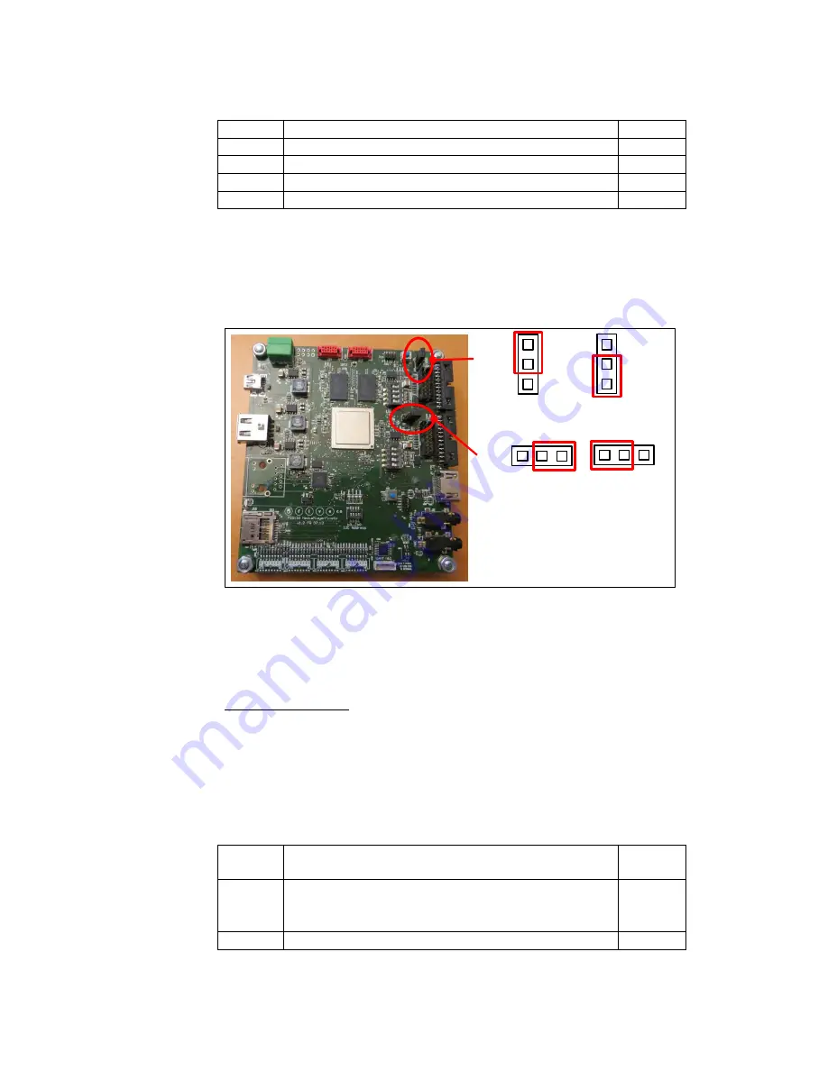
You can also select the voltage of VCC (pin 1, 2, 3) to power the screen
electronic with the Jumper JP1 shown below.
Figure 6 : Screen voltage selection
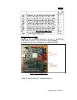
If the screen has its own electronic for backlight, you can power at 12V
with the pin 23, 24(12V) and 19, 20(GND). You can also control it with
the pin 21 (backlight enable) and 22 (Pulse With Modulation, 100% = max
luminance, 0%=no luminance).
Two channels LVDS
If the screen has two LVDS channels, you must use connectors J7 (LVDS1)
and connector J6 (LVDS2). The connector J7 has the same pin assignment
as itself when there is only one channel, but the differentials pairs are only
for odd pixels.
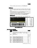
The pins assignments for J6 (LVDS2) are described below:
Table 2 : Pin Assignment of J6 (LVDS2)
SIGNAL
NAME
DESCRIPTION
PIN(s)#
VCC
Screen electronic power supply (3.3V or 5V) can be
selected with JP2. Be careful use the same voltage as
JP1.
1, 2, 3
GND
Power Ground
4, 9, 10,
JP1
JP2
VCC= 5V
VCC= 3.3V
VCC= 5V
VCC= 3.3V


