14 / 28
FMod-IPECMOT 48/10 User Manual v2.5
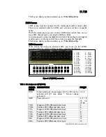
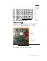
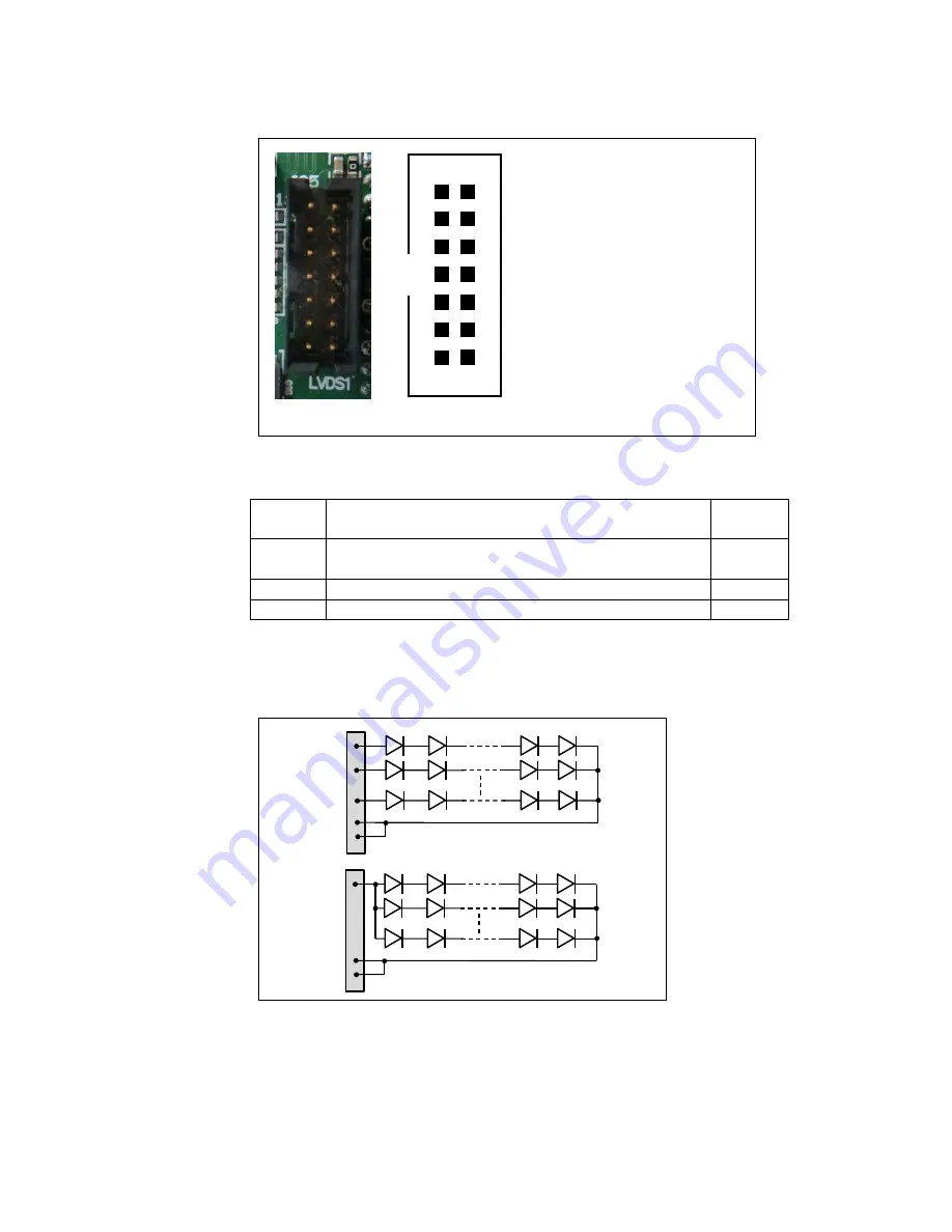
Figure 8 : J11 (Backlight current) connector
Table 3: Pin Assignment of J11 (backlight current)
SIGNAL
NAME
DESCRIPTION
PIN(s)#
Lx+
Anode for 1 Line Led (a line is several leds
connected in serial configuration). Max 80mA/line
1-10
COM+
Anode for all Backlight Unit
11, 12
COM-
Cathode for all Backlight Unit
13, 14
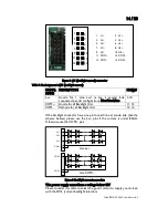
If the backlight connector have one pin for each line at anode side (like the
scheme bellow) please use the Lx+ pins if the current is under 80mA.
Otherwise use the COM+ pins.
Figure 9: Backlight current connection
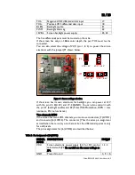
This power supply cannot have a voltage below 12V.
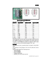
Please consider this table to select the good current to supply your screen
with the SW2 (current backlight selection).
1. L1+
2. L2+
3. L3+
4. L4+
5. L5+
6. L6+
7. L7+
8. L8+
9. L9+
10. L10+
11. COM+
12. COM+
13. COM-
14. COM-
1
3
5
7
9
11
13
2
4
6
8
10
12
14
Use Lx+
L1+
L2+
Lx+
COM-
Use COM+
COM+
COM
-


