background image

1 / 71


3 Axes  

Ethernet Control Board 


FMod-IPAXESCTRL 


H:1.1 / F:1.11


User’s Manual 


Version 1.1 


FMod-IPAXESCTRL  User Manual v.1.1 

Summary of Contents for FMod-IPAXESCTRL

Page 1: ...1 71 3 Axes Ethernet Control Board FMod IPAXESCTRL H 1 1 F 1 11 User s Manual Version 1 1 FMod IPAXESCTRL User Manual v 1 1 ...

Page 2: ...egistered trademark of Sun Microsystem Warning This device is not intended to be used in a medical life support or space product Any failure of this device that may cause serious consequences should be prevented by implementation of backup systems The user agrees that protection against consequences resulting from device system failure is the user s responsibility Changes or modifications to this ...

Page 3: ...0 16 11 04 XG First revision history Since 1 8 1 3 1 1 21 04 05 XG Add IP SUBNETMASK register 0x13 Add TCPCONNECTIONSOPENED register 0x1A Easy change IP with broadcast Add relative coordinate with relative zero Add AXISxPOSITIONOFFSET registers relative offset Since 1 11 1 6 FMod IPAXESCTRL User Manual v 1 1 ...

Page 4: ...play 14 Keyboard 15 Trackball 16 LEDs 17 SOS button 18 5 TCP UDP Server 19 General 19 TCP HTTP port 80 20 TCP UDP Control port 8010 21 Checksum calculation 23 6 Java Applet 24 Overview 24 Main Panel 25 Board s communication settings Panel 26 Keyboard settings panel 27 LCD text Panel 29 Modes Axes settings Panel 30 7 Reference zero absolute relative 31 8 Registers management 32 Memory Organization ...

Page 5: ...rating conditions Package contents 1 Axes Ethernet Control board FMod IPAXESCTRL This manual optional Power Supply Power over Ethernet IEEE802 3af Hub injector 110 240 VAC 50 60Hz 48v 350 mA FMod IPAXESCTRL User Manual v 1 1 ...

Page 6: ...pacity Power 220uF 50mOhm ESR Power consumption 0 8W 65mA when idle Vcc 7 V Without LCD Trackball 25mA when idle Vcc 24 V 15mA when idle Vcc 48 V Power consumption 1 2W 150mA when idle Vcc 7 V With LCD Trackball 45mA when idle Vcc 24 V 25mA when idle Vcc 48 V FMod IPAXESCTRL User Manual v 1 1 ...

Page 7: ...t communicates independently with the selected FMod IPxxMOT devices motor control cards through the Ethernet network It can even be easily configured using its internal web pages http server onboard with any standard web browser A 4x20char LCD can be connected to locally display information and a trackball keyboard are the available inputs to handle the axes LCD display 4 20 character Keyboard 4 L...

Page 8: ...compliant Switch the communication between them is done through the UDP IP protocol An optional computer PC Mac can be connected to the same network to the Ethernet 10BaseT compliant Switch in order to configure the parameters of the axes control card The same Switch used to connect the FMod IPAXESCTRL and the FMod IPDCMOT48 1 5 can be connected to the Internet network under an ADSL modem router o...

Page 9: ...d Layout JP3 SOS button J1 IN Power IN Power J7 Ethernet RJ45 J4 Keyboard 2x4 Keyboard 4x4 J5 Trackball J3 LEDs indicator J8 LCD display 75 7 69 5 64 3 3 2 70 5 Height max 20mm FMod IPAXESCTRL User Manual v 1 1 ...

Page 10: ... consequences should be prevented by implementation of backup systems The user agrees that protection against consequences resulting from device system failure is the user s responsibility motion fiveco com www fiveco com FMOD IPAXESCTRL INPUT supply 7 48V DC 1 5 W MAC 00 50 C2 30 8x xx IP 169 254 5 1 The MAC Address is the 48bits unique identifier on Ethernet networks The IP Address can be modifi...

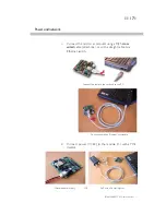
Page 11: ...le direct link or with a straight cable to a Ethernet switch Connect the cable to the card and to the PC Connection with an Ethernet crosscable 2 Connect power 7 48V to the module Or with a POE injector Discrete power supply OR PoE with a Power injector FMod IPAXESCTRL User Manual v 1 1 ...

Page 12: ...C the software ask you to select the one which is connected to the same network as the FMod IPAXESCTRL 7 The software suggests you a new IP address without the last byte Choose a new IP that is not already used on your network and click the Change IP address button That s it The card has a new address and a new subnet mask the same as your PC They are automatically saved into EEPROM You can now co...

Page 13: ...ded to enable disable each of them You have just to connect a peripheral before the power up of the card Note It is better NOT to deplug the peripherals when the system is powered Power supply The card can be powered in two modes WARNING do NOT use both at the same time 1 POE Power Over Ethernet 48V only 350 mA on connector J7 RJ45 pins 4 5 7 8 Swapped polarity works too Compatible with IEEE 802 3...

Page 14: ...l CFAH2004A TMI JP with LSI HD44780 driver inside blue backlit with white characters pictured on the left The connector on the FMod IPAXESCTRL board has the same pin configuration as the one of the LCD allowing an easy flat cable connection but the LCD has to be used in 4bits data mode only Board J8 connector pinout 1 GND 2 5V 3 VO Contrast 4 RS 5 R W 6 E 7 nc 8 nc 9 nc 10 nc 11 DB4 12 DB5 13 DB6 ...

Page 15: ... Line 2 5 Line 1 6 Line 0 Board J4 down connector pinout 4x4 version 1 Column 0 2 Column 1 3 Column 2 4 Column 3 5 Line 2 6 Line 3 7 Line 1 8 Line 0 The next scheme shows the position of each key on the Keyboard useful for the configuration A B C D A B E F G H E F I J I J K L M N M N O P Column 0 1 2 3 0 1 Line 0 1 2 3 Connector Connector FMod IPAXESCTRL User Manual v 1 1 ...

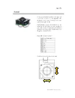
Page 16: ...EWATRON model LP150 5FV00 is the reference for this board It is also possible to use other kinds of trackballs with different resolution or even gravity independency ex Megatron model 816TC Board J5 connector pinout 1 not connected 2 nc 3 nc 4 5V 5 Xa 6 Yb 7 Ya 8 Xb 9 nc 10 GND Trackball connector pinout and axes Axe 2 Axe 1 FMod IPAXESCTRL User Manual v 1 1 ...

Page 17: ...ball axes 1 and 2 When an axis is found and is ready to receive data then its corresponding LED is on and if an axis is suspended its LED is off Actually it is possible to drive an axis for ex axis1 without modifying the other one ex axis2 which has been put in a suspended state with the press of a Keyboard button Notes a No led exist for axis 3 because it cannot be driven by the trackball b The L...

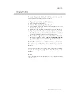
Page 18: ...ed during running This action is useful when the user has lost the actual IP address of the card and temporarily needs to connect to it without changing all the parameters of the card Only the IP address is overwritten with the SOS IP address written on the sticker on the card 169 254 5 1 This new IP will be valid only after that all TCP IP connections web pages too will have been closed In this c...

Page 19: ...ts are available using the TCP protocol Port 80 for HTTP communication Port 8010 Access to the control port Only one port is accessible through the UDP protocol Port 8010 Access to the control port You will find a detailed description on the different ports in the next pages Note The board allows up to 4 simultaneous TCP connections That means for example that 4 users can connect to the 80 port to...

Page 20: ... IE Netscape Mozilla Safari and type the IP address of the card Ex type http 169 254 5 1 index htm in the address bar of the browser and the index htm page will be loaded If you don t use a browser software you can write your own software that can access to the HTTP port and ask for a specific webpage and then retrieve the page content in the html code FMod IPAXESCTRL User Manual v 1 1 ...

Page 21: ...te Parameters Data 5 Checksum 2 bytes Control Sum of packet s bytes Function ID The specific code for each function can be found on the next page of this manual Transaction ID The user defines himself the values of the Transaction ID Normally each packet transaction communication request should have a different ID even if this is not mandatory When the FMod IPAXESCTRL receives a command packet it ...

Page 22: ...345 The two previous entries are replicated for each register that has been asked for reading Checksum 16 bits 0xnnnn Example WRITE register s value command Byte Number of bits Example 0x00 Write 0x0022 16 bits 0x0022 0x02 TransactionID 16 bits 0x1B34 0x04 Number of bytes in command 16 bits 0x0003 0x06 Register Addresses 8 bits 0x02 0x07 Register value 8 64 bits 0x1234 The two previous entries are...

Page 23: ... to 32 bits result is 32bits 0x0000 last result 3 Add last result to the 32 bits accumulator Try the Loop 4 Convert accumulator in two 16bits words 5 Add this two 16bits words result is 16bits word 6 If an overflow occurs with the last addition Carry add 1 to the last result 7 Last result is the final result Example in hexadecimal for this packet 0x0021 Æ 0x0000FFDE Read 0x1234 Æ 0x0001EDA9 TransI...

Page 24: ...he IP address of the module Here is an example with default address http 169 254 5 1 The applet is downloaded from the module to your computer and runs as a local process on your computer So you need to use a web browser that is compatible with Java 1 1 Please note that on a MS Windows based computer a delay of some seconds can occur when you download the JAVA applet due to an OS NetBios issue The...

Page 25: ...tions LCD text Display parameters Axes settings Parameters of the motor control cards Save user settings sends a command to the board in order to save the current running USER configuration on the board Restore user settings is used to restore the USER s configuration from EEPROM Restore factory settings To restore the FACTORY s default settings Note You will find more details about user factory p...

Page 26: ...ve closed their connection begun with the previous IPaddress At that moment the IP address in the address bar of the browser will have to be changed to access the applet again Subnet mask useful only for special UDP directed broadcast TCP Watchdog Maximum time before automatic disconnection if the client does not send any packet Module name of your choice Module hardware MAC address read only FMod...

Page 27: ...ey of the keypad is represented by a character from A line0 column0 to P line3 column3 and the corresponding list of available functions Just press the corresponding scrollmenu and choose the function your want to program for this specific button FMod IPAXESCTRL User Manual v 1 1 ...

Page 28: ... 41 Increment axis 2 in Mode 2 15 Mode 3 42 Decrement axis 2 in Mode 2 16 Axis 1 ON OFF 43 Increment axis 3 in Mode 2 17 Axis 2 ON OFF 44 Decrement axis 3 in Mode 2 18 Axis 3 ON OFF 45 Increment axis 1 in Mode 3 19 Axis 1 suspended while pressing 46 Decrement axis 1 in Mode 3 20 Axis 2 suspended while pressing 47 Increment axis 2 in Mode 3 21 Axis 3 suspended while pressing 48 Decrement axis 2 in ...

Page 29: ...on display axe m1 pos state axe m1 pos state X pls X 123 456 pls 789 Ok See description of LCD MODE i TEXT register p 55 for more details The measured value contains 8 digits 1 more for the sign On the display the character represents one digit of that value If less than 9 are present on a line the least significant digits would be skipped Other ASCII characters can be used also between with the v...

Page 30: ...ettings HIDRatio DiplayRatio The ratio between the motor pulses and the value displayed with the Display ratio Example value of 10 means 1 motor pulse 10 increment on LCD The ratio between human interface devices keyboard or trackball and motor pulses with HID ratio Example value of 10 means 1 trackball pulses 10 increment on motor FMod IPAXESCTRL User Manual v 1 1 Display ratio LCD display M Ethe...

Page 31: ...ters could make no sense because their reference 0 is changed Especially if a home position homing is done at power up 2 FMod IPxxMOT POSITION register is kept unchanged but an offset value will be added locally in FMod IPAXESCTRL In both cases the value displayed is the same and all the interaction But with the 0 relative reference the inside FMod IPxxMOT reference will not change That is very im...

Page 32: ...ER Parameters Saved FACTORY Parameters Saved SOS IP address 5 1 2 3 4 VOLATILE DATA Action Number and description SaveUserParameters 0x03 function During standard power up or calling RestoreUserParameters 0x04 function RestoreFactoryParameters 0x05 function SaveFactoryParameters 0x06 function For integrators engineers only By pressing SOS Button after power up By pressing SOS Button during power u...

Page 33: ...0 1 TCPWATCHDOG 0x15 21 16 MODULENAME 0x1A 26 1 TCPCONNECTIONSOPENED General configuration 0x20 32 4 DISPLAYOPTIONS 0x21 33 4 TRACKBALLOPTIONS 0x22 34 4 KEYBOARDOPTIONS 0x23 35 16 KEYBOARDFUNCTIONS 0x24 36 1 MODE 0x28 40 1 LCDCONTRAST 0x29 41 80 LCDMODE1TEXT 0x2A 42 80 LCDMODE2TEXT 0x2B 43 80 LCDMODE3TEXT Axis1 0x30 48 4 AXIS1POSITIONOFFSET 0x31 49 6 AXIS1MACADDRESS 0x32 50 4 AXIS1IPADDRESS 0x33 5...

Page 34: ...2MODE2DISPLAYRATIO 0x46 70 4 AXIS2MODE2HIDRATIO 0x47 71 4 AXIS2MODE3DISPLAYRATIO 0x48 72 4 AXIS2MODE3HIDRATIO Axis3 0x50 80 4 AXIS3POSITIONOFFSET 0x51 81 6 AXIS3MACADDRESS 0x52 82 4 AXIS3IPADDRESS 0x53 83 4 AXIS3MODE1DISPLAYRATIO 0x54 84 4 AXIS3MODE1HIDRATIO 0x55 85 4 AXIS3MODE2DISPLAYRATIO 0x56 86 4 AXIS3MODE2HIDRATIO 0x57 87 4 AXIS3MODE3DISPLAYRATIO 0x58 88 4 AXIS3MODE3HIDRATIO FMod IPAXESCTRL U...

Page 35: ...TYPE Unsigned Int 16bits LH LL MODEL Description Product identifier composed with a Type and Model number It defines which kind of module it is Normally different TYPE modules are not software compatible Example Module with TYPE 0x00040000 means Type 4 4 IP axes controller Model 0 Limits None Active Each time the processor is running FMod IPAXESCTRL User Manual v 1 1 ...

Page 36: ...Firmware identifier composed with a Version and Revision number Normally same Version with different Revision is backward compatible Example Firmware 0x00010007 Version 1 Revision 7 is compatible with all earlier revisions of the same version ver 1 0 to 1 6 But it has new functionalities which are deactivated by default or code optimizations Limits None Active Each time the processor is running FM...

Page 37: ... Write Control 0x02 RESETCPU Restart processor Write only Register Size Register structure Unit 0 Bytes none none Description Restart the CPU of the board The communication will be lost Active Each time the processor is running FMod IPAXESCTRL User Manual v 1 1 ...

Page 38: ...ET 0x32 AXIS1IPADDRESS 0x33 AXIS1MODE1DISPLAYRATIO 0x34 AXIS1MODE1HIDRATIO 0x35 AXIS1MODE2DISPLAYRATIO 0x36 AXIS1MODE2HIDRATIO 0x37 AXIS1MODE3DISPLAYRATIO 0x38 AXIS1MODE3HIDRATIO 0x40 AXIS2POSITIONOFFSET 0x42 AXIS2IPADDRESS 0x43 AXIS2MODE1DISPLAYRATIO 0x44 AXIS2MODE1HIDRATIO 0x45 AXIS2MODE2DISPLAYRATIO 0x46 AXIS2MODE2HIDRATIO 0x47 AXIS2MODE3DISPLAYRATIO 0x48 AXIS2MODE3HIDRATIO 0x50 AXIS3POSITIONOF...

Page 39: ... Control 0x04 RESTOREUSERPARAMETERS Restores saved values Write only Register Size Register structure Unit 0 Bytes none none Restore the user parameters from EEPROM See SAVEUSERPARAMETERS 0x03 register list Active Each time the processor is running FMod IPAXESCTRL User Manual v 1 1 ...

Page 40: ...tory default Write only Register Size Register structure Unit 0 Bytes none none Description Restore factory parameters See SAVEUSERPARAMETERS 0x03 register list Active Each time the processor is running SAVEUSERPARAMETERS must be done after this function for next reboot with these parameters FMod IPAXESCTRL User Manual v 1 1 ...

Page 41: ...or engineers and not for end user Use it when all parameters have been approved for an application It saves in EEPROM all configurable registers for both factory parameters and user parameters Warning This function also executes the SAVEUSERPARAMETERS function See SAVEUSERPARAMETERS 0x03 saved register s list Active Each time the processor is running Do not change any of these parameters during 1 ...

Page 42: ...ed 2 s cplt Int 16 HH HL 16 bits fixed point LH LL Volt Description Input Voltage Limits Max 0x7FFFFFFxx 32 767 996 Min 0x000000xx 0 0 Step 0x000001xx 0 004 Example When read 0x00234567 2311527 Voltage 35 27 2311527 65536 Information Below effective 6 5 V 0x00068000 this value has no meaning Active Each time the processor is running FMod IPAXESCTRL User Manual v 1 1 ...

Page 43: ...ion Each information warning error is contained in 2 bits the first one shows the current state the next one shows if this state appeared previously Only the bits that show the states in the past can be cleared by writing 0x00000000 to WARNING register Bits when set Warnings 0 31 Reserved for future use Default bits 31 0 0x00000000 Active Each time the processor is running FMod IPAXESCTRL User Man...

Page 44: ... settings Write Read Register Size Register structure Unit 4 Byte Unsigned Int 32 bits each bit independent none Description Settings for ethernet communication Bits 0 31 Reserved for future use Limits None Default bits 31 0 0x00 0x00 0x00 b 00000000 Active Each time the processor is running FMod IPAXESCTRL User Manual v 1 1 ...

Page 45: ... Register Size Register structure Unit 6 Byte 6 x Unsigned Byte none Description Standard hardware unique identifier world for each device on an ethernet network Information If user writes into this register the address won t be modified This register is available only for informational purpose FMod IPAXESCTRL User Manual v 1 1 ...

Page 46: ...nd UDP IP The values 255 0xFF and 0 0x00 are reserved for broadcast and network address and should not be used in this register The module will change for a new IP address only when all of its communications ports are closed Do not forget to execute the SAVEUSERPARAMETERS function in order to save the IPaddress Example For the IP 192 168 16 14 0xC0 0xA8 0x10 0x0E write 0xC0A8100E to IPADDRESS FMod...

Page 47: ...l of its communications ports are closed Do not forget to use a SAVEUSERPARAMETERS command Example For the IP 10 2 6 45 and subnet mask 255 255 0 0 IP address class A Æ netID 10 subNetID 2 and hostID 6 45 Note If you do not want to use subnets use the following subnet mask when IP address is IP address range Subnet mask 1 x x x 127 x x x 255 0 0 0 Class A addresses 128 x x x 191 x x x 255 255 0 0 ...

Page 48: ...he TCP watchdog is deactivated But in this case if the client crash during connection the communication won t never be closed on the module s side For the reason that maximum 4 communications are allowed at the same time on the module one of them will be blocked If the client crash four times all of the 4 communication will be blocked and the module will have to be reset Limits Max 255 Default 30 ...

Page 49: ...II name R W Register Size Register structure Unit 16 Byte 16 only x Unsigned Byte CHAR none Description Name and description of the module Example For the name Hello Module extend to 16 byte the name Hello Module 5x space 16 Byte So write 0x48656C6C 6F204D6F 64756C65 20202020 FMod IPAXESCTRL User Manual v 1 1 ...

Page 50: ...Write Control 0x1A TCPCONNECTIONSOPENED Number of TCP connections that are opened Read Only Register Size Register structure Unit 1 Byte Unsigned Int 8 bits none Description Number of users connected to the card using TCP Value can be 0 to 4 FMod IPAXESCTRL User Manual v 1 1 ...

Page 51: ...ONS Bit to bit settings Write Read Register Size Register structure Unit 4 Byte Unsigned Int 32 bits each bit independent none Description Bits when set DISPLAYOPTIONS 0 31 Reserved for future use Default bits 31 0 0x00000000 Active Each time the processor is running FMod IPAXESCTRL User Manual v 1 1 ...

Page 52: ...IONS Bit to bit settings Write Read Register Size Register structure Unit 4 Byte Unsigned Int 32 bits each bit independent none Description Bits when set TRACKBALLOPTIONS 0 31 Reserved for future use Default bits 31 0 0x00000000 Active Each time the processor is running FMod IPAXESCTRL User Manual v 1 1 ...

Page 53: ...IONS Bit to bit settings Write Read Register Size Register structure Unit 4 Byte Unsigned Int 32 bits each bit independent none Description Bits when set KEYBOARDOPTIONS 0 31 Reserved for future use Default bits 31 0 0x00000000 Active Each time the processor is running FMod IPAXESCTRL User Manual v 1 1 ...

Page 54: ... in Mode 1 Repeat 0x0A Increment axis 3 Repeat 0x25 Inc axis 3 in Mode 1 Repeat 0x0B Decrement axis 3 Repeat 0x26 Dec axis 3 in Mode 1 Repeat 0x0C Change mode 1 2 3 1 0x27 Inc axis 1 in Mode 2 Repeat 0x0D Mode 1 0x28 Dec axis 1 in Mode 2 Repeat 0x0E Mode 2 0x29 Inc axis 2 in Mode 2 Repeat 0x0F Mode 3 0x2A Dec axis 2 in Mode 2 Repeat 0x10 Axis 1 ON OFF 0x2B Inc axis 3 in Mode 2 Repeat 0x11 Axis 2 O...

Page 55: ...et of other registers are in use It can be changed with the communication protocol or with a Keyboard functions Each mode has a specific LCD display and a specific input output ratio input HID output Display Here is the list of registers selected with MODE 1 0x29 LCDMODE1TEXT 0x33 AXIS1MODE1DISPLAYRATIO 0x34 AXIS1MODE1HIDRATIO 0x43 AXIS2MODE1DISPLAYRATIO 0x44 AXIS2MODE1HIDRATIO 0x43 AXIS3MODE1DISP...

Page 56: ...ibility is good If you continue to increase it you will not probably see a real difference but the LCD will not appreciate after a long time Too high levels can be detected after a long use 1 day when older characters image retention still appear on the LCD positions filled with blank space characters Each LCD has an operating voltage pin Vo depending of LCD type and temperature Typically at 25 C ...

Page 57: ...he sign are displayable So the value range is 16 777 216 to16 777 215 With bigger values MAX is displayed and with lower values MIN is displayed To define the place of each character put in the text If not all 9 are defined the least significant characters are skipped For example if 07 654 321 is the result of a multiplication the 2 LSB are useless only 7 will shows the good result 076543 The 2 la...

Page 58: ...2 LCDMODE2TEXT Mode s 2 display text Write Read Register Size Register structure Unit 80 Byte 80 x Char Unsigned Byte none Description When register MODE 2 the text defined with LCDMODE2TEXT is displayed on the LCD See LCDMODE1TEXT 0x29 for more details FMod IPAXESCTRL User Manual v 1 1 ...

Page 59: ...3 LCDMODE3TEXT Mode s 3 display text Write Read Register Size Register structure Unit 80 Byte 80 x Char Unsigned Byte none Description When register MODE 3 the text defined with LCDMODE3TEXT is displayed on the LCD See LCDMODE1TEXT 0x29 for more details FMod IPAXESCTRL User Manual v 1 1 ...

Page 60: ...eate an offset with corresponding POSITION and INPUT register of axis 1 When this register is updated with Key function Set zero absolute or Set zero relative its value is automatically saved in User EEPROM Limits Max 0x7FFFFFFFF 2 147 483 647 Min 0x80000000 2 147 483 648 Default 0 Active Each time the processor is running to disable relative reference write 0 or press Key with function Set zero a...

Page 61: ...ad only Register Size Register structure Unit 6 Byte 6 x Unsigned Byte none Description Standard ethernet network s hardware unique identifier for axis number 1 Information This register is available only for informational purpose Default 0xFFFFFFFFFFFF while a connection has not already been made FMod IPAXESCTRL User Manual v 1 1 ...

Page 62: ...umber 1 used for UDP IP To disable the use of this axis write 0x00000000 to this register The values 255 0xFF are reserved for broadcast and network address and should not be used in this register Default 169 254 5 5 Axis 1 default IP address of module FMod IPDCMOT or FMod IPECMOT 169 254 5 6 Axis 2 169 254 5 7 Axis 3 Example For the IP 192 168 16 14 0xC0 0xA8 0x10 0x0E write 0xC0A8100E to AXIS1IP...

Page 63: ...escription While MODE 1 only For axis 1 only The incoming position integer value of the axis is multiplied with this value and the result integer value is displayed on the corresponding axis line on the LCD Default 1 0 Example If you want to display micrometers while MODE 1 and 1000 increments of axis 1 correspond to 1um set AXIS1MODE1DISPLAYRATIO to 0 001 1 1000 Active Each time the processor is ...

Page 64: ... axis the human interface device HID output is multiplied with AXIS1MODE1HIDRATIO and the result is send to the motor s new goal Default 1 0 Example For big motor movement an HID increment a key pressed once or a trackball pulse can result to multiple position increments on the motor side AXIS1MODE1HIDRATIO 1 For small motor movement multiple HID increments a key pressed repetitively or several tr...

Page 65: ... Read Write Control 0x35 53 AXIS1MODE2DISPLAYRATIO Convert the display value Write Read Register Size Register structure Unit 4 Byte Float 32 bits none Description While MODE 2 only For axis 1 only See AXIS1MODE1DISPLAYRATIO 0x33 for details FMod IPAXESCTRL User Manual v 1 1 ...

Page 66: ...ead Write Control 0x36 54 AXIS1MODE2HIDRATIO Convert human input to motor goal Write Read Register Size Register structure Unit 4 Byte Float 32 bits none Description While MODE 1 only For axis 1 only See AXIS1MODE1HIDRATIO 0x34 for details FMod IPAXESCTRL User Manual v 1 1 ...

Page 67: ... Read Write Control 0x37 55 AXIS1MODE3DISPLAYRATIO Convert the display value Write Read Register Size Register structure Unit 4 Byte Float 32 bits none Description While MODE 3 only For axis 1 only See AXIS1MODE1DISPLAYRATIO 0x33 for details FMod IPAXESCTRL User Manual v 1 1 ...

Page 68: ...ead Write Control 0x38 56 AXIS1MODE3HIDRATIO Convert human input to motor goal Write Read Register Size Register structure Unit 4 Byte Float 32 bits none Description While MODE 3 only For axis 1 only See AXIS1MODE1HIDRATIO 0x34 for details FMod IPAXESCTRL User Manual v 1 1 ...

Page 69: ...gister concerned See Axis 1 0x40 0x48 All Axis 2 registers 0x30 0x38 The use of these registers 0x40 0x48 is the same as described for AXIS 1 but applied to AXIS 2 Please refer to the corresponding pages in this manual FMod IPAXESCTRL User Manual v 1 1 ...

Page 70: ...gister concerned See Axis 1 0x50 0x58 All Axis 3 registers 0x30 0x38 The use of these registers 0x50 0x58 is the same as described for AXIS 1 but applied to AXIS 3 Please refer to the corresponding pages in this manual FMod IPAXESCTRL User Manual v 1 1 ...

Page 71: ...71 71 FMod IPAXESCTRL User Manual v 1 1 Contact address FiveCo Innovative Engineering PSE C CH 1015 Lausanne Switzerland Tel 41 21 693 86 71 Fax 41 21 693 86 70 www fiveco com info fiveco com ...

Reviews: