17 / 71
LEDs
The FMod-IPAXESCTRL is provided with a connector for
4 LED
(J3).
They give information about the mode (1, 2,
3) of the board and the state (activity or not) of the axes.
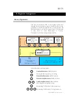
Here is the LED’s layout:
0 1 2 3
Board Mode
Axis
Board Mode
The different modes define the way the input (trackball
and Keyboard) and output devices (LCD display) interact
with the physical system (commands sent to the motor).
See “Axes parameters Panel” in “Java applet” chapter for
more detailed information.
Mode 1
= LED0 on, LED1 off
0 1
Mode 2
= LED0 off, LED1 on
0 1
0 1
Mode 3
= LED0 off, LED1 off
Axis State
The LEDs are especially useful to overview the mode on
how the axes are controlled by the trackball (axes 1 and
2). When an axis is found and is ready to receive data,
then its corresponding LED is on; and if an axis is
“suspended” its LED is off. Actually it is possible to drive an
axis (for ex: axis1) without modifying the other one (ex:
axis2) which has been put in a “suspended” state with the
press of a Keyboard button.
Notes: a) No led exist for axis 3 because it cannot be driven by the trackball.
b) The LEDs display the information in any case, even if the LCD is not connected.
The board drives the lower pin (Cathode /-) of the LED
and the upper (Anode /+) is connected to 5V. An
onboard 1kOhm resistor is connected in series to limit the
current to ~3mA.
Board
J3
Connector:
3 mA
Contro
ller
Board Connector
(one for each led)
5V
1k
1
Led 0 resolution mode 1
2 5V
3
Led 1
resolution mode 2
4 5V
5
Led 2
axis 1 ON/OFF
6 5V
7
Led 3
axis 2 ON/OFF
8 5V
FMod-IPAXESCTRL User Manual v.1.1


