9
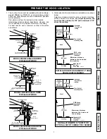
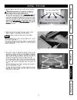
3. Run power cable to installation location. Refer to the
instructions included with the selected blower / rough-in
kit (sold separately) for details on installing the rough-in
plate. Install the rough-in plate so that the wiring box is
located on the right side as you are facing the hood.
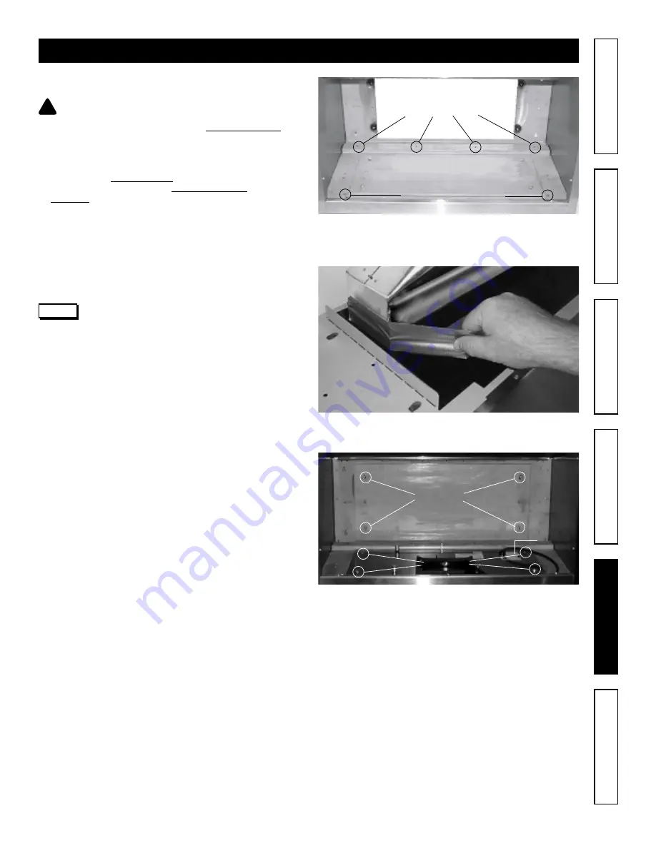
For ducting through back of hood, remove existing plate
from inside back of hood and attach to inside top of hood
to cover hole. Secure to threaded studs with same (4)
nuts.
For ducting through top of hood, existing plate remains in
place on inside back of hood.
Connect ducting to transition or rough-in plate as you are
installing the rough-in plate. Use duct tape to make all
joints secure and air-tight.
Plate on top of hood
Locknuts
Rough-in plate on back of
hood
Wiring
cover
Locknuts
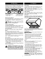
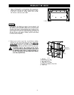
1. Rest the back cavity of the hood on the wood mounting
strip.
!
CAUTION: Hold the hood until it is completely
secured to the wood mounting strip.
Secure hood to wood strip with (4) screws #8 - 3/4” (for
30” and 36” width hoods) or (6) screws (for 48” and 60’’
width hood) provided at location shown. Drill (2) 3/16” size
holes into the drywall for wall anchors through the existing
holes in the inside hood back in the locations shown. Then
install the (2) wall anchors and attach the hood to these
anchors with the remaining #8 - 3/4” screws and the (2)
washers provided.
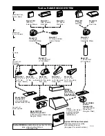
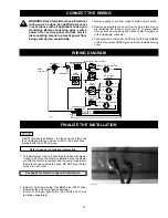
2. Attach transition (if required) to blower rough-in plate.
Refer to page 6 for available model numbers.
Use duct tape to make all joints secure and air-tight.
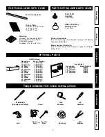
INSTALL THE HOOD
NOTE
Model FBK600 blower plate connects directly to 7” round
duct without a transition.
The exterior blower model 332H utilizes a model 332KR
mounting plate which connects directly to 10” round ductwork
without a transition.
Warranty
Safety
Cleaning
Operation
Installation
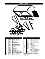
Service Parts
HD0064
HD0049
HD0063
Mounting screw locations
Wall anchor locations
Top of hood (inside view)
Back of hood (inside view)


