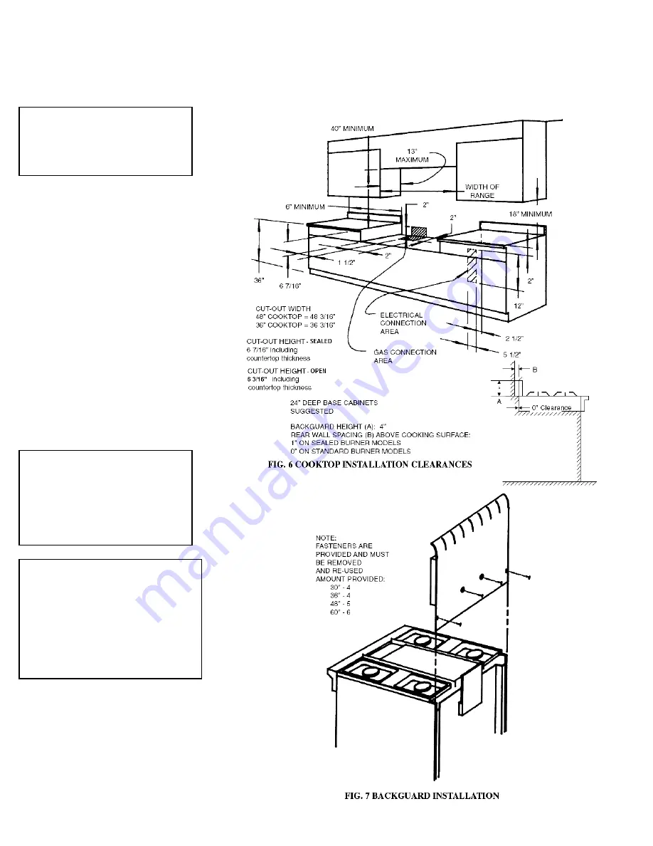
Backguard Assembly
The backguard, located in the top pack
with the range, must be installed prior to
placing the range in position for gas
hookup. See FIG. 7.
Positioning/Leveling
To position the range use a lift jack or
enough manpower to lift the range
completely. Avoid sliding, pushing, or
pulling the range because this increases
the possibility of bending the legs or the
coupling connectors and could also result
in damage to the floor covering.
Ranges and cooktops must be level to
obtain proper cooking results. Ranges
adjust from 35 ⅞” to 37 ⅞” or 2” max.
All units must be level front-to-back and
side-to-side. See FIG. 2.
Cooktops must be installed in a cut-out
and on a level surface, as illustrated in
FIG. 6.
Adjustments
Appliances are set for use with Natural
gas or Propane (LP) gas. The factory
orifice setting is indicated by a second
prefix letter in the model number. The
letter “T” indicates Natural gas setting.
Letter “P” indicates Propane (LP).
NOTE: COOKTOPS DO NOT HAVE LEVELING LEGS.
CABINET SUPPORT MUST BE LEVEL.
NEVER BLOCK THE
FLOW OF AIR FOR
COMBUSTION OR
VENTILTION. SEE FIG. 2.
ALL ADJUSTMENTS
AND/OR CONVERSIONS
MUST BE MADE BY THE
INSTALLER OR
SERVICING UTILITY
DURING INSTALLATION.
SEALED BURNER MODELS
ARE FACTORY SET FOR
THE GAS FOR WHICH THEY
ARE TO BE USED. THEY
CANNOT BE CHANGED
FROM ONE GAS TO
ANOTHER WITHOUT
FACTORY AUTHORIZATION.
6
Summary of Contents for TPN335-BGW
Page 1: ...24 30 36 48 and 60 Range Models 36 and 48 Cooktop Models Your exact model may not be pictured ...
Page 22: ...22 ...
Page 23: ...WIRING DIAGRAMS 23 ...
Page 24: ...24 ...
Page 25: ...25 ...
Page 26: ...26 ...
Page 27: ...27 ...
Page 28: ...28 ...
Page 33: ...33 ...
Page 35: ...NOTES ...
Page 36: ...Part No 188 6C043 01 11 ...


