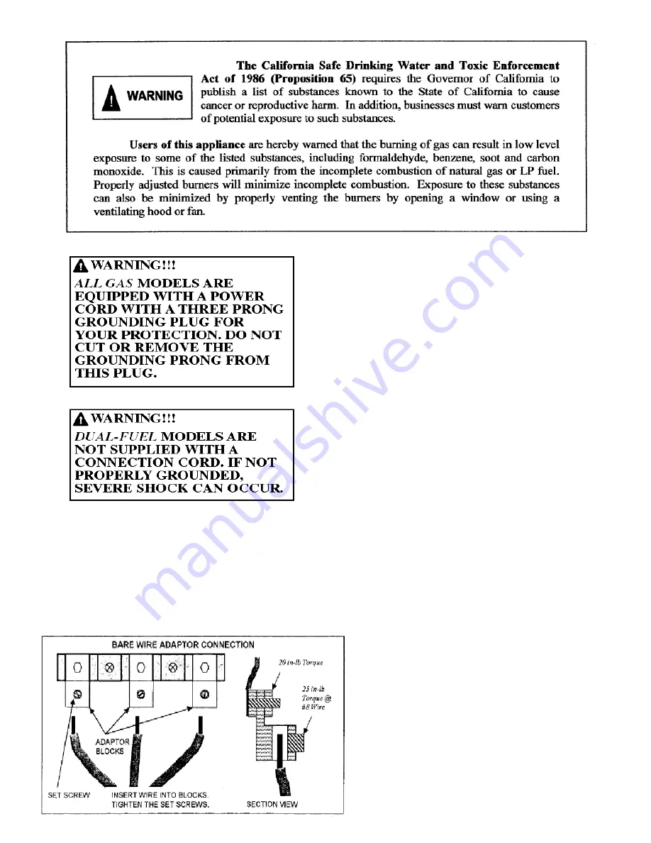
It is strongly suggested that your electric range be connected
by means of a cord utilizing copper conductors. Copper has
always proven itself to be the most dependable conductor.
However, many homes may be wired to connect to a range by
means of aluminum wiring. This is not an ideal situation, and
we urge you to have a qualified electrician change to a copper
cord connection. If this is not possible, bare wire connections
can be made with the terminal adapter kit packed with the
range.
Electronic Ignition
Ranges and cooktops have top ignitor electrodes. When
a top burner knob is turned to the LITE position,
electrodes will spark at a rate of approximately 1½
pulses (sparks) per second. On sealed burner models, the
sparking will stop once the burner has ignited. On open
burner models, rotate the knob slightly clockwise to stop
sparking once lit.
In the event of a power failure you may need to light the
top burners with a match. Do so by holding a lit match
near the surface burner and turning the knob counter-
clockwise to the LITE position.
Spark Modules
The heart of an electronic spark system is the module
that is located either in the burner box, at the bottom of
the appliance, or behind the service access panel on
electric oven models. There is sufficient wiring to
withdraw the module assembly to check the connections,
make repairs or replacement. If sparking does not occur
when the top burner control is on, see page 34 for
troubleshooting tips.
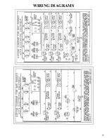
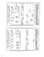
Wiring Diagrams
Wiring diagrams are located in this Use and Care manual
(pages 23 to 29). One is also located behind the control
panel near the griddle/grill knob or on the back of the
access panel beneath the electric oven, depending on the
model.
NOTE: Burner rates specified on the rating plate of the
range apply for elevations up to 2,000 feet above sea
level. For locations where altitudes are higher than 2,000
feet, the BTU rated input should be reduced four percent
for each 1,000 feet higher than 2,000 feet above sea
level. If this adjustment is necessary, contact a qualified
service technician.
9
9
Summary of Contents for TPN335-BGW
Page 1: ...24 30 36 48 and 60 Range Models 36 and 48 Cooktop Models Your exact model may not be pictured ...
Page 22: ...22 ...
Page 23: ...WIRING DIAGRAMS 23 ...
Page 24: ...24 ...
Page 25: ...25 ...
Page 26: ...26 ...
Page 27: ...27 ...
Page 28: ...28 ...
Page 33: ...33 ...
Page 35: ...NOTES ...
Page 36: ...Part No 188 6C043 01 11 ...


