background image

13

6  Operating:

  6.1 Preparing:

  1. Insert the spiral-shaped metal holder into the corresponding opening of the soldering  

      iron stand.

  2. Soak the viscose cleaning sponge with clean water and drain it well before replacing it  

      in the sponge tray.

  3. The soldering tip is mounted into the shaft and fixed by a safety socket to the  


      soldering  iron. Change the soldering tip only at the cooled down soldering iron. In    

      order to do so, unscrew the union nut at the soldering iron and push off the safety    

      socket. Now the soldering tip is exposed and you can pull it off carefully. The screw   

      connections should be inspected regularly regarding their tight fitting and, if required,  

      be tightened accordingly. 

  4. Fix the soldering stand to the right side of the soldering station by plugging in. 


  The soldering iron may not be operated without the soldering tip in any case.

  6.2 Connecting:

  Connect the mains plug of the soldering station with the 220 - 240 V AC / 50 Hz mains   

  socket, while the mains switch is turned off to the 0-status.


Now the soldering station is ready to use.

  6.3 Adjusting the Temperature:


1. Switch on the soldering station by turning the mains switch into the I-status. The  


      soldering station is heating up now.

  2. By using the rotary switch, the soldering temperature can be adjusted steplessly, also  

      during use at every time.


In case of defects the soldering station has to be switched off immediately,  


  disconnected from mains and checked regarding possible causes of the error.


6.4 Handling:

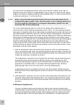
Use suitable soldering wires and handle the soldering station in a correct way. This is 

prerequisite for impeccable soldering operation. We recommend electronics soldering wires 

with colophony solder core. In no case solder cores should contain halogens. The solder 

core within the solder wire liberates the soldering spot from solder-inhibiting contaminations 

and oxides and prevents the producing of new oxide during soldering. 

Summary of Contents for AP 2

Page 1: ...Bedienungsanleitung Manual Notice d utilisation Manual Istruzioni per l uso Lötstation soldering station AP 2 Art No 51091 ...

Page 2: ... production and workshops It comes with soldering iron stand for the soldering iron with sponge tray and viscose cleaning sponge as well as an analog temperature adjustment A compact stabile and protective insulated housing is included The high power 40 48 Watts soldering iron heats up quickly and is driven by safety low voltage Stepless adjusting is possible between 150 450 C 2 Intended Use Your ...

Page 3: ...operation In the following cases you CANNOT expect an assured operation visible damages e g faults of isolation damage of the housing no function long storing under bad conditions improper transport A defective soldering station may not be put into operation but must be disconnected from mains and protected against further use Repairing such as assembling and disassembling the housing is only allo...

Page 4: ...le soldering material such as solder paste solder tincture etc During transport observe the details listed in the Chapter Specifications and imple ment measures suitable for transport e g use the original package For questions defects mechanical damages malfunctions and other functional problems which cannot be resolved by this guide please contact your dealer for repair or replacement as describe...

Page 5: ... Connecting Connect the mains plug of the soldering station with the 220 240 V AC 50 Hz mains socket while the mains switch is turned off to the 0 status Now the soldering station is ready to use 6 3 Adjusting the Temperature 1 Switch on the soldering station by turning the mains switch into the I status The soldering station is heating up now 2 By using the rotary switch the soldering temperature...

Page 6: ...t will become passive after a while and disable to absorb solder anymore 1 Hold the cleaned and well tinned soldering tip heated up to the set soldering tempera ture to the soldering wire and to the spot being soldered Now the solder core flows and cleanes the surface of the metal parts being soldered and then the soldering tip in order to make the electrically conducting connection The soldering ...

Page 7: ...nd Liability The producer grants a 2 years warranty to a new device As the manufacturer has no influence on installation warranty of the product only applies to the product If any fault or damage is detected on your device please contact your dealer and provide your sales slip or invoice as evidence of the purchase if necessary Your dealer will repair the fault either on site or send the device to...

Page 8: ...tive 2012 19 EC WEEE No 82898622 12 CE Declaration This device corresponds to EU directives 2004 108 EC and 2006 95 EC With the CE sign Fixpoint a registered trademark of the Wentronic GmbH ensures that the product is conformed to the basic standards and directives These standards can be requested online on www wentronic com The mentioned directives replace all former national permissions in the E...

Page 9: ...17 ...

Reviews: