Fixturlaser GO Pro Manual 2
nd
edition
7.11
ALIGNMENT
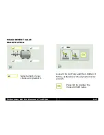
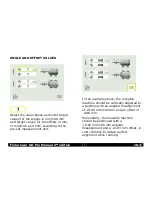
Adjust the angular error by placing
shims under the bolts as required
(negative bolt value means that shims
should be added.) The angular error is
displayed live in the first direction when
the sensors are placed in position
number 1, and in the second direction
when they are placed in position
number 2.
Now adjust the parallel offset in both
directions by moving the machine. The
parallel offset is displayed live in the
first direction when the sensors are
placed in position number 1, and in the
second direction when they are placed
in position number 2.
Check that both the angular value and
the parallel offset lie within the required
tolerances once the adjustments are
completed.
Alignment is now complete. To confirm
the result, re-do the measurement.
Re-measure.
Summary of Contents for GO Pro
Page 1: ...MANUAL Fixturlaser GO Pro user s...
Page 2: ......
Page 4: ...Fixturlaser GO Pro Manual 2nd edition September 2011...
Page 12: ...Fixturlaser GO Pro Manual 2nd edition 3 4...
Page 52: ...Fixturlaser GO Pro Manual 2nd edition 7 12...
Page 64: ...Fixturlaser GO Pro Manual 2nd edition 10 6...
Page 86: ...Fixturlaser GO Pro Manual 2nd edition 14 8...
Page 91: ......


