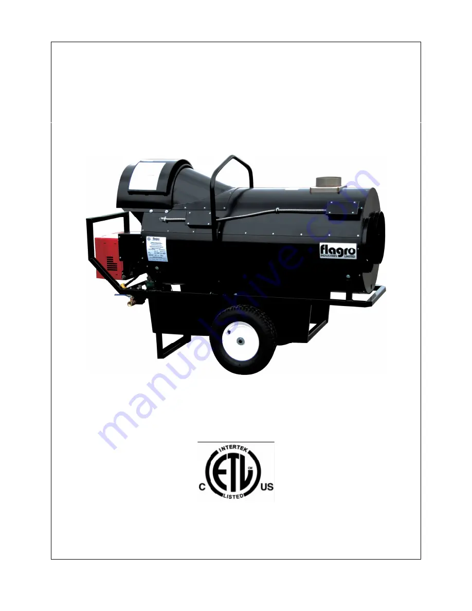
background image


OPERATING INSTRUCTIONS MANUAL  

(Please retain for future reference) 


For


FVNP-400 INDIRECT FIRED SPACE HEATERS 


CERTIFIED FOR USE IN CANADA AND U.S.A. 

As per Standard ANSI Z83.7/CSA 21.4 2000 Gas Fired Construction Heaters / Unattended Type. 


FLAGRO INDUSTRIES LIMITED 

ST. CATHARINES, ONTARIO 

CANADA 


Summary of Contents for FVN-400

Page 1: ... for future reference For FVNP 400 INDIRECT FIRED SPACE HEATERS CERTIFIED FOR USE IN CANADA AND U S A As per Standard ANSI Z83 7 CSA 21 4 2000 Gas Fired Construction Heaters Unattended Type FLAGRO INDUSTRIES LIMITED ST CATHARINES ONTARIO CANADA ...

Page 2: ...NS MANUAL LABELS ETC CONTACT THE MANUFACTURER WARNING FIRE BURN INHALATION AND EXPLOSION HAZARD KEEP SOLID COMBUSTIBLES SUCH AS BUILDING MATERIALS PAPER OR CARDBOARD A SAFE DISTANCE AWAY FROM THE HEATER AS RECOMMENDED BY THE INSTRUCTIONS NEVER USE THE HEATER IN SPACES WHICH DO OR MAY CONTAIN VOLATILE OR AIRBORNE COMBUSTIBLES OR PRODUCTS SUCH AS GASOLINE SOLVENTS PAINT THINNER DUST PARTICLES OR UNK...

Page 3: ...of fuel gases and heat producing products in specific applications Your local authority can advise you about these SPECIFICATIONS Model FVNP 400 Input 390 000 btuh Fuel Propane Natural Gas Manifold Pressure 1 5 W C Propane 2 0 W C NG Maximum Inlet Pressure 13 0 W C Propane 10 0 W C NG Ignition Direct Spark Ignition Thermostat Control Air Circulation 2500 cfm Fuel Consumption 18 5 lbs hr Propane 38...

Page 4: ...ted at least 10ft 3m from any propane gas cylinder This heater shall not be directed toward any propane gas container within 20ft 6m CONNECTING THE CYLINDER If cylinders are used to supply the heater no cylinders smaller than 100lb capacity shall be used These cylinders must supply a vapor withdrawal only 1 All cylinder connections must be made using a wrench to tighten the POL fitting 2 Be sure t...

Page 5: ... 8 0 IN WC NG 4 0 IN WC This heater must be supplied by pressures indicated on the approval label Over pressure may cause controls to fail DO NOT supply this unit with more than psig 14 0 in W C Note A second stage regulator must be installed if the supply pressure exceeds psig FUEL This heater is a dual fuel heater and operates on propane natural gas The manifold pressures are listed on the appro...

Page 6: ...appropriate gauge extension cord is used 12 3 AWG at 50 Feet 10 3 AWG at 100 Feet POWER SUPPLY INDICATOR LIGHT The power supply indicator light will help detect any faulty power supplied to the heater such as grounding issues reverse polarity or missing poor connections Warning Light Indications Green Light Meets Power Requirements Solid Red Light Reverse Polarity Solid Red Green Light Ground Issu...

Page 7: ...cting should be inspected periodically for tearing and or wear marks Ducting should be stored in a dry area when not in use FLUE PIPE Flue pipe connection must terminate with a vertical run at least 2 ft long Horizontal runs should have a rise ratio of 1 in 10 away from the heater The chimney should have a 0 2 W C draft to ensure safe operation of the unit The vent outlet on the heater is 6 diamet...

Page 8: ...VENT TERMINATION MUST BE A MINIMUM OF 2FT HIGHER THAN ANY POINT WITHIN 10FT B MAXIMUM HORIZONTAL RUN IS 30FT NOTE 90deg ELBOW 10ft HORIZONTAL VENT ALLOWANCE 45deg ELBOW 5ft HORIZONTAL VENT ALLOWANCE C VENT TERMINATION IN HORIZONTAL POSITION MUST BE MINIMUM 4ft FROM ANY COMBUSTABLE SURFACE D EXTERIOR VERTICAL VENT TERMINATION MUST BE A MINIMUM OF 2ft NOTE ALL VENT TERMINATIONS MUST HAVE A RAIN CAP ...

Page 9: ... combustible materials gasoline and other flammable vapors and liquids 4 The flow of combustion and ventilation air must not be obstructed Be sure to check the fan assembly and ensure that the motor and blade are operating properly 5 Compressed air should be used to keep components free of dust and dirt build up Note Do not use the compressed air inside any piping or regulator components 6 Fan Lim...

Page 10: ... must be left in the OFF position for 30 seconds to prevent the burner from locking out 3 When using a generator for electrical supply make sure the generator is properly grounded and generator is at a 60Hz frequency 4 In the event that a generator is being used and the generator runs out of fuel make sure the heater switch is in the OFF position before restarting generator failure to do so may da...

Page 11: ... service SAFE OPERATION PRECAUTIONS 1 For use with propane or natural gas only See approval label 2 Use switch to shut down the heater Do not try to shut down the heater by unplugging the electrical cord 3 Do not plug anything other that the thermostat into the Thermostat plug 4 Follow electrical requirements shown on rating plate and or Electrical requirements section of this manual 5 Before remo...

Page 12: ... B The proper number on the manual AIR ADJUSTMENT PLATE 1 should line up with the SETTING INDICATOR 4 on the fan housing cover Once set the air ad justment plate should be secured in place by tightening SCREWS 2 and 3 C The final position of the air adjustment plate will vary on each installation Use in struments to establish the proper settings for maximum CO2 NOTE Variations in flue gas CO2 and ...

Page 13: ...ng the location of the temperature feeler gauge holes This will provide maximum performance of the unit in different applications If supply air is warm 5 C indoor application Turn the temperature feeler gauge so that the holes are parallel with the heat exchanger This will help the fan switch to remain cool and not overheat See following If supply air is cold under 5 C Turn the temperature feeler ...

Page 14: ...usted for warmer weather conditions Failure to do so may result in burning out fan switches not covered under warranty PRINCIPAL BURNER COMPONENTS 1 Air Damper Optional Delete 2 Air Gate Lock screws 3 Wiring Terminal Block 4 Air Pressure Switch 5 Motor 6 Lockout Lamps and Reset Button 7 Cover Screw 8 Rubber Grommet 9 Capacitor BURNER DIMENSIONS ...

Page 15: ... version Gasket thickness is 4 millimeters ELECTRODE AND FLAME PROBE ADJUSTMENTS IMPORTANT Do not turn the ignition electrode Leave it as shown in the drawing If the ignition electrode is put near the ionization probe the amplifier of the control box may be damaged TYPICAL GAS TRAIN LAYOUT FIELD SUPPLIED RIELLO SUPPLIED ...

Page 16: ...OPERATED GAS SUPPLY PRESSURE TEST POINT FIELD SUPPLIED MAIN GAS VALVE V1 24V OR 120V OPERATED SINGLE STAGE GAS TRAIN PIPE DIAMETER SIZE S BURNER G120 1 2 NPT REDUCED AT COMBUSTION HEAD TO 3 8 BURNER S G200 G400 3 4 NPT GAS BURNER MANIFOLD TEST POINT GAS SUPPLY PRESSURE RANGES NATURAL GAS PRESSURE MIN 4 0 WC MAX 10 0 WC L P PROPANE GAS PRESSURE MIN 8 0 WC MAX 13 0 WC FIELD WIRING DIAGRAM ...

Page 17: ... SWITCH on the 525 SE CONTROL BOX is equipped with a contact allowing remote sensing of burner lockout The electrical connection is located on the CONTROL BOX terminal 4 as indicated Should burner lockout occur the 525 SE CONTROL BOX will supply a power source of 120 Vac to the connection terminal The maximum allowable current draw on this terminal is 1 A ...

Page 18: ...PARTS DIAGRAM FVNP 400 FV 408 FV 438 FV 434 FVP FR FV 403 FV 402 FV 405 FV 401 FVNP 424 FV P08 FV P10 FV P11 FV 404 FV 406 FV P01 FV P02 FV P06 FV 437 FV 407A FV 448 FV P05 ...

Page 19: ...FV 446 FV 447 2103 E CGA FVNP 428 FVNP 429 FVNP 427 FV 431 HC5 64 FV 437 FV 407A FV 407G FV 433B FV 433 FV 450SI FV 414B FV 409 FV 411 FVNP 430 ...

Page 20: ...EXPLODED FVNP 400 SPARE PARTS LIST ...

Page 21: ...FVNP 3005834 Capacitor 10µF 14 FVO C7001034 Burner motor 16 FVNP 3006356 Universal mounting flange 33 FVNP 3950372 Long combustion head 279T2 34 FVNP 3006696 Drawer assembly elbow 35 FVNP 3007276 Electrode assembly 36 FVNP 3007265 Electrode ionization clamp 37 FVNP 3007277 Flame rod assembly 38 FVNP 3007300 Manifold 39 FVNP 3007290 Natural gas tube 40 FVNP 3005854 Semi flange 2 required 41 FVNP 30...

Page 22: ... FV P09 CONTROL BOX LID FV P10 LIMIT BOX DOUBLE HOLE FV P11 LIMIT BOX SINGLE HOLE FV P12 LIMIT BOX LID FV 409 TOGGLE SWITCH ON CONTROL BOX FV 410 GREEN LIGHT ON CONTROL BOX PRIOR TO 2009 FV 411 RED LIGHT ON CONTROL BOX FV 414 THERMOSTAT PLUG ON CONTROL BOX FV 414A THERMOSTAT PLUG ON CONTROL BOX 2008 FV 414B THERMOSTAT PLUG ON CONTROL BOX 2011 FV 415 FEMALE CONNECTOR FOR FV THA FV 415A FEMALE CONNE...

Page 23: ...RNER SUB BASE FVNP 3005447 GAS PRESSURE TEST POINT ADAPTER FVNP 3005834 CAPACITOR FVNP 3006356 MOUNTING FLANGE FVNP 3006688 CHASSIS MOUNTING COLLAR FVNP 3006699 DISTRIBUTOR HEAD MIXING PLATE FVNP 3007223 CHASSIS FRONT PLATE FVNP 3007239 BURNER BACK COVER FVNP 3007276 ELECTRODE ASSEMBLY FVNP 3007277 FLAME ROD ASSEMBLY FVNP 3007288 AIR SWITCH TUBE CONNECTOR FVNP 3007293 AIR TUBE COVER PLATE FVNP 300...

Page 24: ...ACCESSORIES FV HD12 12 X 12 FT HITEX DUCTING FV HD16x25 16 X 25 FT HITEX DUCTING FV THB THERMOSTAT C W 25FT CORD FEMALE PLUG END as of 2011 FVN 426 REPLACEMENT ORIFICE FV VK 6 X 3FT C VENT C W RAIN CAP ...

Page 25: ...TAT FAN MOTOR FVO 400 WIRING SCHEMATIC FV 400 WS 2011 FV 400 SERIES WIRING SCHEMATIC 2011 FLAGRO INDUSTRIES LIMITED SWITCH BURNER REAR HIGH LIMIT SWITCH FRONT HIGH LIMIT SWITCH M1 M1 L1 N G G X RED LIGHT POWER INDICATOR 115 VAC T1 T4 T3 G G ...

Reviews: