Technical Description
AP BIO
400/500/1000/2400
12
FG-DC_10523-GB_AP Bio_IOM-R0-12/2020 • Subject to modifications
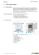
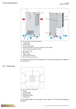
Fig. 4-2
General overview AP BIO 2400
1: Control panel
2: Indoor air inlet
3: Access door with key
4: Pre-filter ISO ePM1 55% (F7) and HEPA H14 AirFend filter
5: Power socket with integrated switch
6: Identification plate
7: Rear casters
8: Clean air outlet
9: Front caster (with brake)
10: Door lock for access with key
For installed components on the individual unit, refer to the data sheets or the quotation
text for the unit.
4.1.2 Control panel
Fig. 4-3
Overview control panel
1: Display
2: Increase button
3: Decrease button
4: Mode setting button
5: On/Off button
For the data displayed on control panel, refer to chapter 7.1 "Overview of the operating
elements".


