background image

eCO Premium™ - Installation & Maintenance

4

FläktGroup DC_9604GB_20190327_R6

Specifications are subject to alteration without notice

6. GOODS RECEIPT

Each product is carefully inspected before shipping. On receipt of 
goods, it is recommended that products are checked to confirm 
that they have not suffered damage during transport. If damage 
is found, then please report this issue to the transport forwarding 
agent, who is responsible for any damage incurred during trans-
port. The usual method of packing is for products to be loaded 
onto pallets and then fastened to them by means of straps. A 
protective film is also generally added to minimise water ingress.
Alternatively, product may sometimes be contained with a self- 
supporting cardboard carton, which is again fastened securely to 
a pallet.

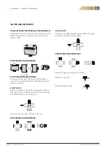
HANDLING AND OFF-LOADING

Before off-loading products, please ensure that the means of 
transport/ lifting is suitable to accommodate to the required 
weight and size capacity. It is recommended that where product 
is shipped on a pallet, a forklift truck should be used.
In accordance with the 89/391/CEE 
standard (and associated updates), 
manual lifting is only admissible up to 
a maximum weight of 20 Kg, between 
floor and shoulder level.
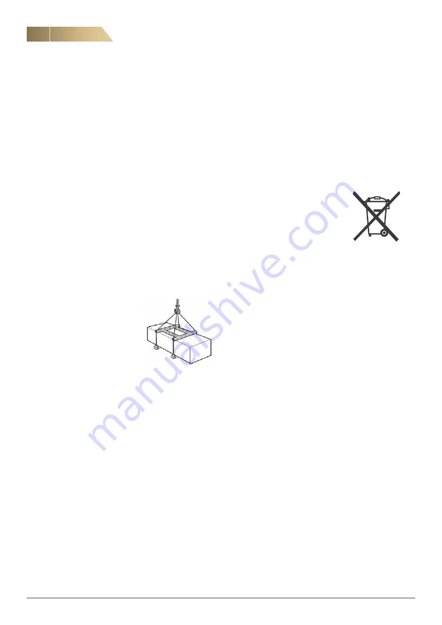
Lift unit into position using spreaders, 
ensuring you have the appropriately 
rated equipment for the weight of the 
unit.

7. EQUIPMENT START-UP

Before operating our product, the following checks must be made:
•  Ensure that product inlet/outlet connections are free from  

obstruction

•  Check that all product components are securely fastened in 

their associated sealing gaskets

•  Manually rotate each fan impeller to ensure that it does not rub 

or bind onto the fan scroll

•  Ensure that any inspection or access doors are closed.

CAUTION:

If fan inlets or discharges are not connected to duct work, please 
ensure that suitable protection guards are fitted before the unit is 
started. Check that electrical connections have been made correct-
ly, especially the earth connection.

IMPORTANT:

Electrical connections must be made by qualified personnel.

9. DISPOSAL

Please ensure that products are dismantled 
and disposed of by qualified personnel in an 
environmentally friendly way, in accordance
with all relevant local and national regulations 
in force.

GOODS RECEIPT, HANDLING, EQUIPMENT START-UP, DIS- AND RE-ASSEMBLY, DISPOSAL

8. DISASSEMBLY AND RE-ASSEMBLY

Before starting any disassembly or re-assembly operation, please 
ensure that the product is isolated from its mains electrical sup-
ply, in order to ensure that fans cannot be run. As disassembly 
and re-assembly are not part of routine maintenance, these 
should be carried out by qualified personnel.

Summary of Contents for eCO Premium

Page 1: ...INSTALLATION AND MAINTENANCE MANUAL eCO PREMIUM...

Page 2: ...rd 20 Schedules 24 Control functions 27 Parameter List 30 15 MINIMUM SPACE REQUIRED FOR THE MAINTENANCE 35 16 CONDENSATION REMOVAL AND DRAIN TRAP 35 17 FITTING INSTRUCTIONS AND MAINTENANCE FOR DUCTED...

Page 3: ...l ktGroup does not accept responsibility for personal injury or damage caused to property resulting from non com pliance with these safety standards or as a result of any non approved product modifica...

Page 4: ...unit into position using spreaders ensuring you have the appropriately rated equipment for the weight of the unit 7 EQUIPMENT START UP Before operating our product the following checks must be made E...

Page 5: ...to facilitate ceiling fastening and levelling We recommend that the unit is fitted and fastened into its correct position before making con nections to ductwork condensate discharge pipe work on the e...

Page 6: ...to be installed into a ceiling void or if there is any kind of height restriction The support brackets can be removed by unbolting 4 x M8 bolts at each corner of the bracket Support brackets Mounting...

Page 7: ...fication 1 Connection incoming supply 2 Control card 2 3 1 4 Locate electrical connection panel on the service side of the unit Unscrew four fixings and remove electrical panel ETHERNET CONNECTION OPT...

Page 8: ...ed using the appropriate screws see figure 2 The cellular plastic which is semi elastic will slowly adapt to the shape of the cables and in doing so the lead through will seal see figure 3 Information...

Page 9: ...VALVES AND ACTUATORS ACCEPTED INSTALLATION METHOD VALVE FOR HEATING AND COOLING The valve and valve actuator can be easily installed with out special tools A particle filter should be fitted before th...

Page 10: ...Modbus RS485 Filter Monitor Extract Optional Not for size 6 with electrical post heater 230V 1 50Hz 400V 3 50Hz Size 6 with electrical post heater Electrical guide for supply and internal fuses Electr...

Page 11: ...ler Water mixing valve Optional CO2 Sensor Optional Control Board Post Heater Electrical Optional Post Heater Water mixing valve Optional External Timer 1 Optional Fan Guard Control Not when using COP...

Page 12: ...for size 6 with electrical post heater NOTE When cooling the supply temperature sensor must be placed after the cooling coil NOTE SV1 Hot Water actuator Accessory connects to connection box near the h...

Page 13: ...trol panel using a screwdriver 2 Lift the display out of the enclosure 3 Push the connection cable through a suitable hole and if needed make an outlet for the cable on side of the cover Mount the enc...

Page 14: ...are universal and available on many menu pages Home key to return to the Home Screen Back button to cancel and return to the previous page Confirm button to confirm and proceed Changing a value Option...

Page 15: ...A HOME SCREEN OVERVIEW Heat recovery active Post heater active Cooling active Defrosting in progress Manual mode CO2 regulation Automatic mode Constant pressure Constant Air Volume Timer 1 Timer 2 Tim...

Page 16: ...IC OPERATION OVERVIEW SHORTCUT TO SET THE TEMPERATURE SET POINT USER SETTINGS See page 17 SHORTCUT TO SET THE TIME AND DATE SELECT OPERATING MODE See page 17 TRICKLE OR LOW SPEED NORMAL OR MEDIUM SPEE...

Page 17: ...TURE STATUS The temperature set point is used to determine when the post heater if fitted starts to warm the supply air entering the property The temperature set point can be adjusted to any temperatu...

Page 18: ...h the spanner button 3 In this menu you set the date time and language It is also possible for installers and service personnel to log in and access additional parameters DATE TIME 2 Set the time and...

Page 19: ...creen via the passcode protected Advanced Settings option Numerous system parameters can be adjusted through the Settings Screen however only those that are relevant and appro priate to the scope of t...

Page 20: ...onstant Air Volume set the desired air flows 3 Constant pressure set the desired pressure 4 CO2 control set the desired CO2 level 2 Choose 2 Run Commissioning Wizard under Settings Login Press 2 1 Sta...

Page 21: ...s the confirm button to proceed to next step Option 1 Use buttons Option 2 Use the numerical keypad confirm with Make the appropriate settings for the supply fan and press the confirm button Enter des...

Page 22: ...re subject to alteration without notice COMMISSIONING WIZARD CONT 2 CONSTANT AIR VOLUME To end the commissioning wizard press the red cross button Press the to continue to schedules See section 9 7 3...

Page 23: ...2 Choose CO2 low limit The value tells if the lower limit shall be trickle or normal speed The speed cannot decrease under this value 3 Set the ratio between exhaust and supply air The exhaust fan is...

Page 24: ...selects the Weekly Schedule adjustment screen to create a timed schedule to run daily in a week SINGLE DATE 1 4 Pressing this option selects the Single Date Schedule adjust ment screen to create a tim...

Page 25: ...ormal 20 C Friday 8 17 Normal 20 C Saturday 10 14 Normal 20 C Other time Stop SCHEDULES CONT EXAMPLE 3 WEEKLY SCHEDULE Below is an example of a weekly schedule configured to run the fans at normal spe...

Page 26: ...other Date Period 4 Schedule has the highest priority and Date Period 1 Schedule the lowest priority If two or more date period schedules have start and end times that clash with each other only the s...

Page 27: ...from standard mode to cascade mode Then control mode is selected by changing the cascade reference to extract air control room control 0 or outdoor temperature compensation 1 Below is a description o...

Page 28: ...e A 0 05 When the sensor gets colder than given setpoint value 4 Cascade B 0 03 When the sensor gets hotter than given setpoint value 5 Min temp 15 C Sets lowest supply air temperature 6 Max temp 25 C...

Page 29: ...Maximal activation time for night cooling 7 PRESSURE OR FLOW CONTROL PRESSURE CONTROL COP ACCESSORY Control principle in which the unit maintains a constant duct pressure Normally used in variable fl...

Page 30: ...de Calculated Set point R 15 35 C FAN STATUS Parameter Type of value1 Range Unit Default value Comments Supply Fan speed R 0 or 30 100 Extract Fan speed R 0 or 30 100 Pressure Supply air R 0 2000 Pa F...

Page 31: ...Control Extract R W Yes No Yes Only Supply Extract as slave R W Yes No No Ratio Supply Extract R W 0 200 100 Supply air pressure Set point R W 0 2000 Pa 150 Extract air pressure Set point R W 0 2000 P...

Page 32: ...ting Cooling Summer Winter Heat pump runs when Winter Cooling pump runs when Summer Pump Motion every day 12 00 12 05 Constant temp Hot Water Coil R W 0 50 C 25 Low limit running temp R W 0 50 C 15 Fr...

Page 33: ...9999 s 60 Filter Alarm Extract R W 0 9999 s 60 Electrical Heater Error R W 0 9999 s 2 Pump Heater Malfunction R W 0 9999 s 2 Frost Protection R W 0 9999 s 2 Alarm Cooling R W 0 9999 s 2 Pump Cooling M...

Page 34: ...4 19 2 Parity R W None Even Odd None Data bits R W 7 8 8 Stop bits R W 1 2 1 8 5 Mac address Mac address R 8 7 Login Settings Auto Logout R W Yes No Yes Set Password R W To change Password 8 8 About...

Page 35: ...d with a condensate drainage point to which a drain trap should be attached to ensure effective evacuation of water during normal operation Any drain trap should be as detailed below and should have a...

Page 36: ...cess opening in the heater must be equipped with a fixed mesh or an intake air device which makes it impossible to touch the element intake The distance from the heater to a duct bend valve filter etc...

Page 37: ...on dimension FILLING VENTING AND DRAINING The water coil collection pipes are equipped with an air venting nipple and a draining nipple The air must be properly vented from the system to ensure good f...

Page 38: ...e following procedure should be followed All work must be carried out by an authorised electrician Switch off the power supply Carefully investigate the reason s why the overheat protection is activat...

Page 39: ...silencer can be rotated if required This is relevant is there are silencers at each end of the unit as they need to be turn upside down to attach the correct spigot on the silencer to the correct spi...

Page 40: ...n terminal 41 and 42 ST1 The wiring diagram for this function can be found in the controls section of this document 1 2 Attach the external shut off damper with actuator by sliding con nector over rub...

Page 41: ...STALLATION AND FITTING INSTRUCTIONS Lower the weather cowl roof onto the weather cowl making sure that the set of M5 nutserts are at the unit end of the roof Secure the weather cowl roof to the weathe...

Page 42: ...nt then the connection plates and fixings on the side to connected to the weather cowl should be removed from the weather roof Connection plates The final step to complete is to attach the side hatche...

Page 43: ...uld be removed for cleaning Make sure not to handle the heat exchangers by touching the thins as these will deform For normal ventilation applications it is mostly satisfactory to clean the inlet and...

Page 44: ...replacement variable dependent on environnemental air pollution dust fume etc 1 3 2 To remove the filters for replacement unscrew by hand the thumb screws in the filter panels Remove these screws from...

Page 45: ...if necessary correct Clogged heat exchanger Clean heat exchanger block Airflow Performance drops after a period of acceptable operation See above Air leak before and or after the fan Damaged impeller...

Page 46: ...al name eCO PREMIUM REDA The machine is designed and manufactured in accordance with the following standards in relevant parts EN ISO 12100 Safety of machinery General principles for design Risk asses...

Page 47: ......

Page 48: ...application area We offer our customers innovative technologies high quality and outstanding performance supported by more than a century of accumulated industry experience The widest product range in...

Reviews: