Commissioning
HyPower-Geko
102
FläktGroup DC-2014-0022-GB 2018-05/R5 • Subject to modifications
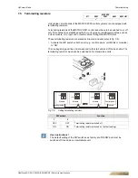
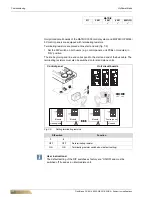
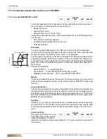
Unit printed circuit boards of the MATRIX 3000 control system and MATRIX OP3X/44/
5X control panels are equipped with terminating resistors.
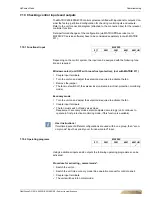
Terminating resistors are placed at line start and end (fig. 7-9):
•
Set the DIP switch on both users (e.g. control panels, unit PCBs or modules) in
“ON” position.
The line beginning and line end correspond to the start and end of the bus cable. The
terminating resistors must also be switched on for stand-alone units.
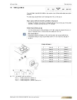
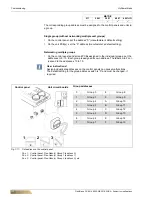
Fig. 7-9:
Setting terminating resistors
DIP switch
Function
1
2
OFF
OFF
No terminating resistor
ON
ON
Terminating resistor switched on (default setting)
MATRIX
511
2001
3001
4001
4001+IO
9
9
9
O
NO
N
O
N
Control panel
Unit circuit boards
99
98
97
96
95
L
110
111
112
102
103
104
105
N
N
STP
STP
120
121
122
123
124
125
N
32
31
73
72
71
70
38
37
36
07
06
15
14
13
12
11
10
35
34
33
N
L
STP
STP
STP
STV
STV
STV
STV
1
STV
N
30
2
STV
ON
110
111
112
120
121
122
123
124
125
130
131
132
140
141
133
134
142
143
144
03
02
01
07
06
15
14
13
12
11
10
18
STP
STP
99
98
97
96
95
L
N
102
103
104
105
N
N
STP
STP
N
N
N
N
75
74
73
72
71
70
05
04
25
24
19
N
L
STP
STP
STP
STP
STV
STV
STV
STV
STV
STV
L
L
N
1
2
ON
110
111
112
120
121
122
123
124
125
130
131
132
140
141
133
134
142
143
144
03
02
01
07
06
15
14
13
12
11
10
18
STP
STP
99
98
97
96
95
L
N
102
103
104
105
N
N
STP
STP
N
N
N
N
75
74
73
72
71
70
05
04
25
24
19
N
L
STP
STP
STP
STP
STV
STV
STV
STV
STV
STV
L
L
N
1
2
ON
L
N
N
N
N
113
114
100
150
151
100
152
153
69
68
67
66
65
64
63
62
Module
Module
Module
Control panel
Line beginning
Line end
User instructions!
The default setting of the DIP switches ex factory are “ON/ON” and must be
switched off if used as an intermediate unit.


