HyPower-Geko
Electrical connection
FläktGroup DC-2014-0022-GB 2018-05/R5 • Subject to modifications
63
6.7
Electrical connection with MATRIX
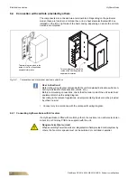
6.7.1 Connecting mains supply voltage for controller
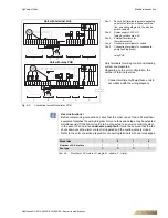
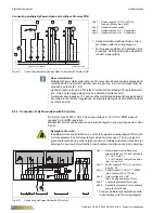
6.7.2 Connecting control cables
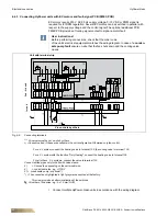
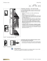
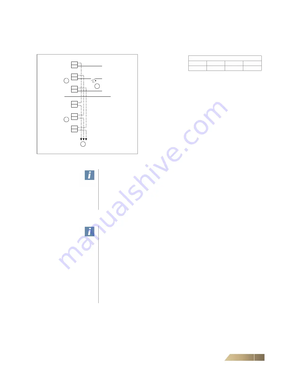
Pos. 1:
Power supply 230 V AC / 50 Hz,
on-site fusing by others max. B 10 A
Pos. 2:
Connection to first unit
Pos. 3:
Connection to second unit
Pos. 4:
To further units
– For units without a condensate pump, the mains voltage is
connected directly to the controller (Pos. 1 and Pos. 3).
– For units with a condensate pump, the connection is com-
pleted using a separate terminal strip in the switch box
(e.g. with 3x1.5 mm2 NYM).
•
Apply the mains supply voltage in accordance with the wiring
diagram.
Fig. 6-9:
Connecting mains supply voltage
User instructions!
Power supply for slave units can be provided by the master unit (refer to fig. 6-9,
Pos. 3 and Pos. 4).
The total power consumption of the units must not exceed 10 A. If required, provide
an auxiliary power supply.
According to the relevant regulations, an all-pole isolating device must be provided
by others on site.
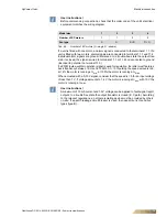
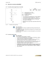
User instructions!
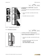
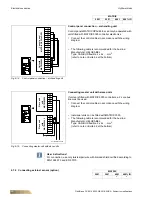
Use the following control cables for connection:
– In order to meet the specifications of the Declaration of Conformity: multi-wire
control cable 0.5 mm
2
with copper weave shielding
– Install the control cable shielding in the FläktGroup units using cable shield
grounding clamps to ensure the best possible electrical contact.
– Apply the shielding with the grounding clamps to a large ground surface area!
Apply the shielding on one side (otherwise transient current can occur).
– The maximum total line length must not exceed 50 m.
– FläktGroup is not assuming any liability in regard to meeting the requirements of
the Declaration of Conformity if other cable types, like foil-type shielding, are
used. Likewise, FläktGroup can not make statements in regard to suitability of
such cable types.
N
N
L
L
PE
PE
PE
L
N
N
N
L
L
PE
PE
1
2
3
4
MATRIX
2001
3001
4001
4001+IO
9
9
9
9


