


Electrical connection
HyPower-Geko
76
FläktGroup DC-2014-0022-GB 2018-05/R5 • Subject to modifications
6.9
Electrical connection of FläktGroup miniature switches/relay PCB for units with AC
fans
HyPower-Geko units can be easily controlled using the CMS, CMT or CET.ACEC
switches.
Depending on the unit model, the following operating modes are possible:
– Operating mode
Only Heating
(2-pipe system)
– Operating mode
Only Cooling
(2-pipe system)
– Operating mode
heating or cooling
(2-pipe system)
– Operating mode
Heating and Cooling
(4-pipe system)
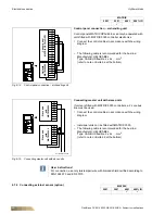
The connection of miniature switches is completed using a factory mounted terminal block
(fig. 6-32 top) or relay PCB (fig. 6-32 bottom). This terminal block is located in the terminal
box or the metal-sheet electric switch cabinet mounted on the medium connection side of
the basic casing (refer fig. 6-1, Pos. 2).
Without a relay PCB
only
one
unit
can be operated at one switch CMS, CMT.
With a relay PCB up to 4 units of different types can be operated with one switch (CMS,
CMT, CET.ACEC).
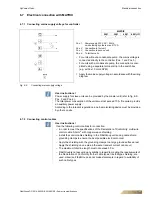
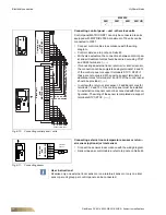
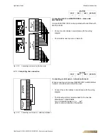
The following wiring diagrams demonstrate the interconnection of a miniature switch
with 2 units for different unit models with a relay PCB.
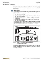
Pos. 1:
Fan control (terminal diagram depending
on selected rotational speed combina-
tion, see wiring diagram in the electric
switch cabinet).
Pos. 2:
Power supply 230 V AC;
fusing by others max. 6 A
Pos. 3:
External terminals for
thermal contacts
Pos. 4:
Connecting terminals for valves
Pos. 5:
Connecting terminals for condensate
pump fault (optional)
relay PCB
Only terminals for wiring control and steering
system are presented.
Depending on the unit configuration, the
number of terminals varies.
•
Connect multiple HyPower-Geko units in
accordance with the wiring diagram.
Fig. 6-32: Connection termial block/relay PCB
Unit with terminal strip
Unit with relay PCB
User instructions!
Before starting with connections, check that the order code of the unit's electrical
equipment matches the wiring diagram. Only one fan speed stage may be activated
simultaneously! In case of a
condensate pump fault
ensure that a triggering leads
to fan shutdown and closing of cooling valve. Refer to the unit connection diagram
for connecting terminals with error messages. According to the relevant regulations,
an all-pole isolating device must be provided by others on-site.


