


Electrical connection
HyPower-Geko
78
FläktGroup DC-2014-0022-GB 2018-05/R5 • Subject to modifications
6.10.2 Operating mode
only heating
–
only cooling
–
heating or cooling
(2-pipe system)
6.10.3 Operating mode
Only Heating
(2-pipe system)
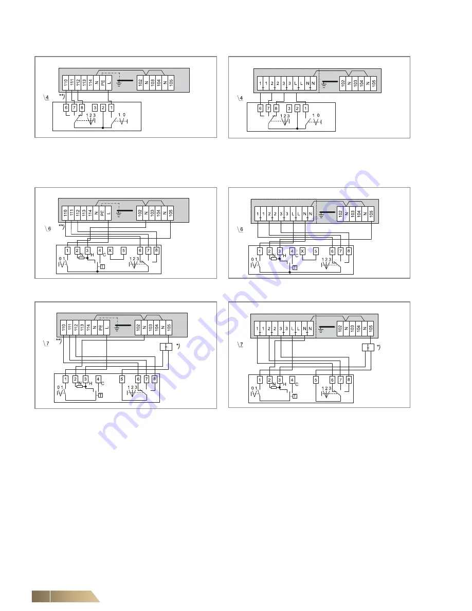
*)
Intermediate terminals must be set by others on-site.
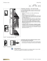
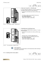
**)
Fan control (terminal diagram depending on selected rotational speed combination, see wiring diagram in the electric switch cabinet.
Fig. 6-34: Manual fan control
(unit with terminal strip)
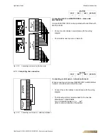
Fig. 6-35: Manual fan control
(unit with relay PCB)
Fig. 6-36: Fan continuous mode and valve control
(unit with terminal strip)
Fig. 6-37: Fan continuous mode and valve control
(unit with relay PCB)
Fig. 6-38: Fan and valve control
(unit with terminal strip)
Fig. 6-39: Fan and valve control
(unit with relay PCB)
CMS
Unit with terminal strip
CMS
Unit with relay PCB
CMT2D
Unit with terminal strip
CMT2D
Unit with relay PCB
CMT2Z
Unit with terminal strip
CMT2Z
Unit with relay PCB


