HyPower-Geko
Electrical connection
FläktGroup DC-2014-0022-GB 2018-05/R5 • Subject to modifications
79
6.10.4 Operating mode
Only Cooling
(2-pipe system)
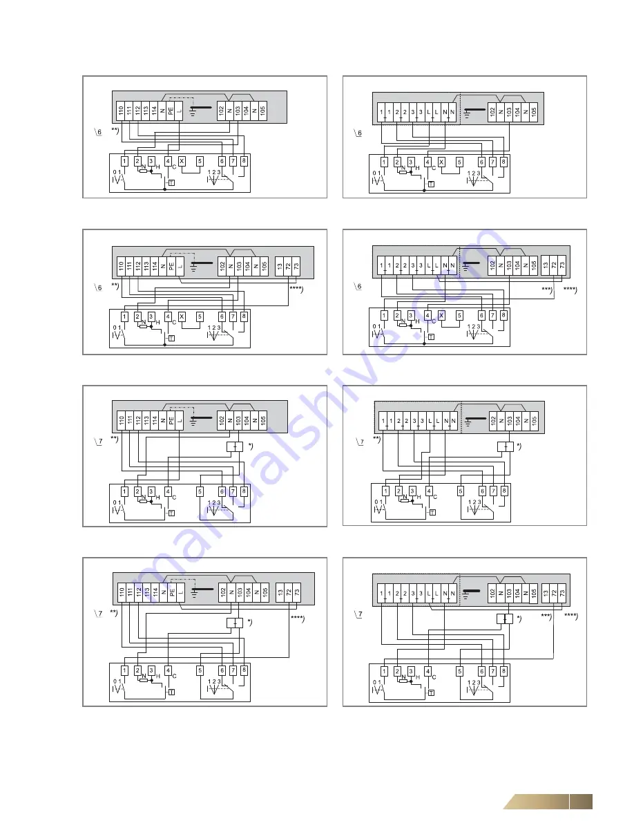
*)
Intermediate terminals must be set by others on-site.
**)
Fan control (terminal diagram depending on selected rotational speed combination, see wiring diagram in the electric switch cabinet.
***)
Signal contact condensate pump fault (for wiring on further units, refer to wiring diagram chapter 6.10.1).
****)
In case of a condensate pump fault, the switch is automatically disconnected from the power supply.
Fig. 6-40: Fan continuous mode and valve control
(unit with terminal strip)
Fig. 6-41: Fan continuous mode and valve control
(unit with relay PCB)
Fig. 6-42: Fan continuous mode and valve control
(unit with terminal strip and condensate pump)
Fig. 6-43: Fan continuous mode and valve control
(unit with relay PCB and condensate pump)
Fig. 6-44: Fan and valve control
(unit with terminal strip)
Fig. 6-45: Fan and valve control
(unit with relay PCB)
Fig. 6-46: Fan and valve control
(unit with terminal strip and condensate pump)
Fig. 6-47: Fan and valve control
(unit with relay PCB and condensate pump)
CMT2D
Unit with terminal strip
CMT2D
Unit with relay PCB
CMT2D
Unit with terminal strip and condensate pump
CMT2D
Unit with relay PCB and condensate pump
CMT2Z
Unit with terminal strip
CMT2Z
Unit with relay PCB
CMT2Z
Unit with terminal strip and condensate pump
CMT2Z
Unit with relay PCB and condensate pump


