HyPower-Geko
Electrical connection
FläktGroup DC-2014-0022-GB 2018-05/R5 • Subject to modifications
87
6.12
Electrical connection of FläktGroup miniature switches CET.ACEC for units with EC fans
The HyPower Geko units can be easily controlled using the CET.ACEC switch.
Depending on the unit model the following operating modes are possible:
– Operating mode
Only Heating
(2-pipe system)
– Operating mode
Only Cooling
(2-pipe system)
– Operating mode
heating or cooling
(2-pipe system)
– Operating mode
Heating and Cooling
(4-pipe system)
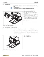
The connection of miniature switches is completed using a factory mounted terminal
strip. These are mounted in the terminal box opposite the medium connection side on
the basic casing is (refer to fig. 6-1).
•
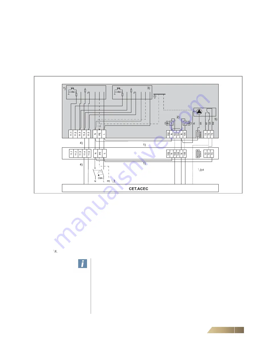
Connect only in accordance with the unit-specific wiring diagram.
Fig. 6-75:
Connecting terminals
1)
N-jumpers must be set by others
2)
Connect valves, if available for unit model. Otherwise only fan control.
For a 4-pipe system, connect the heating valve to terminal 105, the cooling valve to terminal 103.
For a 2-pipesystem with the function "Only Heating", connect the heating valve to terminal 105.
For all other 2-pipe systems, connect the valve to terminal 103.
Connect dotted pipes only for units with valve sleeve.
3 ) Second fan depending on the unit model size.
4 ) control cable fan;
e.g. JY(St)Y
5 ) condensate pump is optional *)
*) The connections highlighted in light gray were executed at the factory.
This view provides a better visualization of the switches.
Number of line wires: e. g.: 5 x 1.5 mm² NYM
User instructions!
Before starting with connections, check that the order code of the unit's electrical
equipment matches the wiring diagram. Always set the N-jumper for the last unit.
In case of a
fan motor fault
ensure that a triggering leads to fan shutdown and cool-
ing valve closure. Refer to the unit connection diagram for connecting terminals with
error messages. According to the relevant regulations, an all-pole isolating device
must be provided by others on-site.
A maximum of 10mA current and 30V voltage can be applied to fault signal outputs.
In a trouble-free state the output transistor is closed (E, C path). According to the
relevant regulations, an all-pole isolating device must be provided by others on-site.
If an earth leakage circuit breaker is used, then use all-current sensitive types (type
B).
Unit with terminal strip
1st u
n
it
2n
d -
4th
unit


