


Electrical connection
HyPower-Geko
88
FläktGroup DC-2014-0022-GB 2018-05/R5 • Subject to modifications
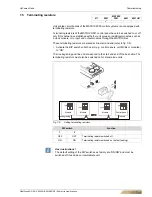
6.12.1 Operating mode
Only Heating
(2-pipe system)
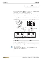
6.12.2 Operating mode
Only Cooling
(2-pipe system)
*)
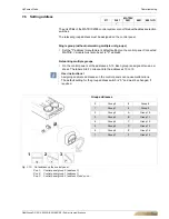
set jumper terminals 13, 14 on-site
***)
Signal contact condensate pump fault (for wiring on further units, refer to wiring diagram chapter 6.12).
****)
In case of a condensate pump fault, the switch is automatically disconnected from the power supply.
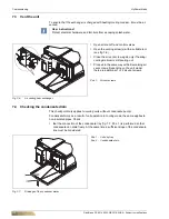
Fig. 6-76: Fan and valve control
(unit with terminal strip)
Configuration
Fig. 6-77: Fan and valve control
(unit with terminal strip)
Configuration
Fig. 6-78: Fan and valve control
(unit with terminal strip and condensate pump)
CET.ACEC
1st unit
2.-4. unit
Parameter 3: SEL0 = 14 and SEL2 = auto
(2-pipe system)
Parameter 4: SEL0 = 16 and SEL2 = OFF
(fan On/Off)
Parameter 5: SEL0 = 18 and SEL2 = auto
Parameter 7: SEL0 = 22 and SEL2 = auto
Parameter 8: SEL0 = 24 and SEL2 = 2
(without sensor)
Parameter 9: SEL0 = 26 and SEL2 = auto
(centrally or via sensor)
CET.ACEC
1st unit
2.-4. unit


