background image

Multi

MAXX

 HG

Commissioning

FläktGroup DC-2011-0141-GB 2018-05/R5 • Subject to modifications

33

7

Commissioning

7.1

Initial commissioning - information for service companies

7.1.1 Initial commissioning of the burner

Before commissioning, check the following:

– Gas distribution does not show any visible deficiencies (should correspond to 

TPG 704 01), setting the main regulating element on the main gas line to the correct 
gas pressure value (for long and complex multi-unit> 2 kPa or> 3 kPa for propane- 
butane distribution) whether the location of the units corresponds to this manual (see 
Chap. 4) and the fuel used corresponds to the fuel setting of the unit 

– Local conditions of the electrical power supply or fusing (are the specifications on 

the unit identification plate taken into consideration?)

– Electrical connections correspond to the wiring diagrams (see Fig. 5-4 to Fig. 5-5)

HAZARDOUS VOLTAGE!

The Multi

MAXX

 HG unit heater may only be electrically installed by skilled 

electricians trained for this task who observe all the valid regulations.

DANGER OF BURNING!

The heat exchanger and the flue-gas venting reach very high temperatures 
in operation.

RISK OF ACCIDENTS DUE TO GAS EXPLOSION!

Before all work at the gas unit heaters, cut off the gas supply with the shut off valve. 
Block the gas main, since it otherwise can lead to a gas flow which can cause an 
explosion, fire etc..
The gas installation of the unit heaters may only be carried out by trained skilled 
workers observing the valid regulations.

NOTE!

The initial commissioning may only be carried out by specialists who are expert 
in the prevailing standards and regulations and are included in the list of authorized 
service companies.

NOTE!

For commissioning of the Multi

MAXX

 HG equipment, observe the valid security 

regulations and standards of the respective countries and the generally recognized 
rules of the technology.

NOTE!

Before commissioning, a required inspection must be conducted according to all the 
prevailing standards. 
Observe the provisions of this Operation Manual at all times during commissioning.
The operator is obligated to conduct regular inspections and maintenance of the 
electrical and gas connections according to all the prevailing standards (see str. 55). 
The first start-up of the Multi

MAXX

 HG unit must be carried out by a professional, 

authorized company .

NOTE!

The torch power connector the burner is sealed with the FläktGroup logo tape. 
Before starting up for the first time, make sure that the tape is not damaged and that 
the burner has not been properly lowered.

Summary of Contents for MULTIMAXX HG 24

Page 1: ...MULTIMAXX HG OPERATION MANUAL ...

Page 2: ... fan for capacity stage 4 B 3x400V 2 speed high speed range wide blade fan for capacity stage 5 D 1x230V 2 speed low speed range wide blade fan for lower capacity stage 4 only for BG2 E 1x230V 2 speed high speed range wide blade fan for capacity stage 5 Q 3x400V 2 speed low speed range sickle blade fan for capacity stage 4 R 3x400V 2 speed high speed range sickle blade fan for capacity stage 5 onl...

Page 3: ...ns 13 2 7 Specification for the Ecodesign Directive passed by the EU Commission 2016 2281 14 3 Shipping and Storage 17 3 1 Shipping 17 3 2 Shipping and handling of the unit 17 3 3 Storage 18 4 Mounting 19 4 1 Load bearing capacity of the installation site 19 4 2 Ceiling mounting 19 4 3 Wall mounting 20 4 4 Safety clearance 22 4 5 Unit mounting 22 4 6 Installing the flue gas pipework 22 4 7 Mountin...

Page 4: ...aintenance 56 9 3 Semi annual maintenance 57 9 4 Break downs 58 10 Disassembly and Disposal 59 10 1 Disassembly 59 10 2 Recycling 59 11 Warranty Conditions 60 11 1 Authorized service companies for warranty and repairs in Germany 60 11 2 Warranty certificate 61 EC DECLARATION OF CONFORMTI 63 Original operation manual Copyright note Disclosing copying distributing or taking any action in reliance on...

Page 5: ...erving the safety instructions in the current operation manual will help avoid the risks ensure economical operation of the unit and let you enjoy the full benefits of the product The safety aspects covered by this chapter are valid for the entire operation manual 1 1 Scope of the operation manual This operation manual provides critical information about the following Shipping Mounting Installatio...

Page 6: ...ifies particular information and prohibitions for avoiding personal injury through gas explosions ENVIRONMENTAL DAMAGE This symbol warns about damage to the environment or refers to all existing national environmental protection regulations EQUIPMENT DAMAGE This section specifies information and precautions for avoiding damages to the MultiMAXX HG Unit Heater RISK OF DAMAGE DUE TO STATIC DISCHARGE...

Page 7: ...oning repair and maintenance work of MultiMAXX equipment observe the respective safety regulations and standards which are valid in the respective countries and generally recognized rules of technology 1 6 Modifications and changes Do not attempt to modify add components or convert the MultiMAXX unit heater in any way Changes or modifications of the unit heater will invalidate the CE conformity an...

Page 8: ... fan optional Pos 1b Sickle blade fan optional Pos 2 Fan section with air inlet nozzle Pos 3 Electrical control box for Multi Operation metal sheet Pos 4 Heat exchanger Pos 5 Heat exchanger casing Pos 6 Reflection plates Pos 7 Flue pipe fitting of air intake Pos 8 Flue gas fitting for smoke exhaust Pos 9 Gas burner Pos 10 Gas burner casing Pos 11 Outlet optional Pos 11 Thermal fuse 11 10 9 7 8 4 2...

Page 9: ...al block Heat exchanger Pos 4 The heat exchanger is simple and robust furnished with a combustion chamber and integrated retractions thereby ensuring an optimal heat transfer between the combus tion chamber and the air to be warmed The heat exchanger is made of high tempera ture resistant steel Heat exchanger casing Pos 5 The heat exchanger casing is assembled by the manufacturer and made of galva...

Page 10: ...table types see unit type code on page 3 The warming of the heat exchanger is ensured by a fully automatic Premix burner The burner can process the following gases natural gas propane butane gas only pro pane and only butane 2 4 Operating conditions Operating temperature 0 C to 40 C Operating voltage 3 x 400 V or 1 x 230 V 50 Hz Protection class IP 40 as per EN 60 529 Fan power consumption see uni...

Page 11: ...ace for installation and maintenance Connection of the unit to the gas mains by means of accessory article ZHG 00xx with internal screw thread R 3 4 without acces sory external screw thread R 1 2 within the unit Dimension BG 2 4 A mm 918 1206 B mm 701 954 C mm 340 370 D mm 80 100 E for fan A B D E mm 81 112 E for fan R mm 66 E for fan Y mm 65 53 E for fan Z mm 53 F mm 110 75 G mm 514 802 H mm 300 ...

Page 12: ...0 2790 0 89 0 21 66 7 0 9 1 13 3 E 1 230V AC Motor 2 speed high speed range HG25 20 30 780 2820 1x230 1 88 0 26 1x230 66 7 1 9 2 13 5 65 1210 4105 2 04 0 43 74 9 1 11 8 19 6 HG45 40 60 700 8455 3 93 0 67 77 7 0 9 2 12 9 112 910 9555 3 71 0 83 82 7 6 10 0 14 5 R 3 400 V AC Motor 2 speed high speed range HG45 40 60 650 8020 3x400 1 87 0 72 1x230 72 6 8 8 9 12 2 112 870 10425 2 72 1 08 79 8 1 10 6 15...

Page 13: ...ner power consumption P ign Emissions of nitrogen oxides NO x Emission efficiency ƞ s flow Seasonal space heating energy efficiency ƞ s h At rated heating capacity P elmax At minimal capacity P elmin In standby mode P elsb kW kW kW mg kWh input energy GCV kW kW kW 2 HG24 A 21 7 13 8 87 8 93 2 0 0 0 0 40 94 6 84 5 0 043 0 030 0 008 HG24 D 21 7 13 8 87 8 93 2 0 0 0 0 40 91 9 82 0 0 043 0 030 0 008 H...

Page 14: ...L 9002 Spare filter for air intake hood roof ZH 3802 ZH 3804 ZH 3808 Filter G2 Filter G4 Filter F7 Bag filter module ZH 360 With filter G2 and G4 made of galvanized steel sheet with or without differential pressure switch Spare filter for bag filter module ZH 3902 ZH 3904 ZH 3908 Filter G2 Filter G4 Filter F7 Mat filter module ZH 370 With filter G2 and G4 made of galvanized steel sheet with or wit...

Page 15: ...sate drain ZHG 4880 Diameter 80 mm Al Pipe with sleeve and with condensate drain ZHG 4810 Diameter 100 mm Al Windproof hood wall ZHG 4980 Diameter 80 mm Al Windproof hood wall ZHG 4910 Diameter 100 mm Al Coaxial windproof hood wall ZHG 7980 Diameter 80 125 mm Al Coaxial windproof hood wall ZHG 7910 Diameter 100 150 mm Al Roof air intake hood ZHG 5080 Diameter 80 mm Al Roof air intake hood ZHG 5010...

Page 16: ...f the delivery note Ship and store unit heaters in original packing EQUIPMENT DAMAGE After shipment check to make sure that the unit is not damaged NOTE Incorrectly delivered quantities or damages caused by shipping must be entered immediately in the shipping voucher or possibly the goods should not be accepted and the manufacturer or supplier immediately informed DANGER DUE TO OVERHEAD LOADS Do n...

Page 17: ...st moisture soiling dust and sand and sun radiant heat Store only in areas protected from weather influences mildews rodents and vibrations The unit heater or the regulator and other accessories may not be stored or operated in areas with salty fog NOTE Allowable storage conditions Air temperature 15 C to 40 C Air humidity max 80 without condensation ...

Page 18: ...ted as a durable and vibration free weight bearer of the unit heater and be checked by a structural engineer or architect if necessary 2 x 4 rivet nuts M8 on the sides of the fan module are provided for mounting the sus pension of the MultiMAXX HG Unit Heater see Fig 2 2 The fixing material is included with the suspensions Unused M8 rivet nut openings should be closed with M8 screws from the trans...

Page 19: ...t for the respective types are listed in following table Tab 2 4 Unit spacing for ceiling mounting see Fig 4 2 In order to achieve a favorable air distribution pattern of the occupied zone we recom mend the following unit spacing Fig 4 2 Unit spacing for ceiling mounting Example of ceiling mounting with mixed air module and ceiling suspension ZHx 5602 see Fig 4 8 4 3 Wall mounting Please observe m...

Page 20: ...wer speed stages and less air volume flow resulting from the pressure loss of the accessory or external pressure loss Examples of the air throw for the individual units are listed in the following table Tab 2 4 Recommended unit distances for wall mounting see Fig 4 4 In order to achieve a favorable air distribution pattern of the occupied zone we recom mend the following unit spacing Fig 4 4 Unit ...

Page 21: ...ved Tab 4 1 and Fig 4 5 1 elbow fitting 90 single type corresponds to 1 m length of a direct pipe with a sleeve as single type One elbow piece 90 coaxial model corresponds to 1 m length of a straight tube with coupling sleeve coaxial type or 2 m of the single type 4 6 1 Maximum lengths of the flue gas pipework NOTE When installing a heating unit observe safety clearances of burnable materials at l...

Page 22: ...ing of a mixed air unit with coaxial flue gas pipework There may be no wall openings above the exit of the flue gas pipework Unit type Combination of the flue gas pipework Unit heating capacity QT Length of the flue gas pipework for a unit with suction side accessories L2 Length of the flue gas pipework for a unit without suction side accessories L2 kW m m HG 24 Coaxial 25 5 6 Coaxial 1 m Single L...

Page 23: ...xial flue gas pipework Fig 4 8 Ceiling mounting of a mixed air unit with coaxial flue gas pipework ZH 3200 ZH 5100 ZH 5502 ZH 200 ZH 360 ZH 2500 possibly ZH 2600 ZH 5602 ZH 350 ZH 4900 ZH 200 ZH 360 ZH 2500 event ZH 2600 NOTE As the first accessory module for the mixed air units mount either a flexible discharge connector ZH 2500 or a rectangular duct 150 ZH 2600 Refer to mounting examples in Fig ...

Page 24: ...ing to all prevailing standards and ensure regular maintenance see str 55 NOTE For the commissioning of the MultiMAXX HG units the valid safety regulations and standards of the respective countries and the generally recognized rules of technology must be observed NOTE The electrical connection must be carried out with an all pole separator with a contact breaker gap of min 3 mm Furthermore a power...

Page 25: ...her on site fuse protection of the fan are used 5 2 2 Connection of actuators of the mixed air modules blocking dampers and outlets The standard design of the actuators of the mixed air modules involves so called two wire technology without limit switch Wiring diagram of the respective actuators see Chap 5 4 and 5 5 5 3 Multi operation For Multi operation the control system is a mandatory accessor...

Page 26: ... type an independent combination is possible for regulation The connection is carried out according to the wiring diagram Fig 5 4 and Fig 5 5 5 3 2 Remote control board OSHG 0 RDDO control remote for a unit group Fig 5 3 Remote control board OSHG 0 RDDO The OSHG 0 RDDO remote control board is designed for remote control of units and becomes a control board and clips for mounting on a DIN rail with...

Page 27: ...iagram of MultiMAXX HG fans D E Y 1 x 230V 50Hz with OSHG 0 000M OSHG 0 EC0M control panel or OSHG 0 RDDO remote control board Fig 5 4 Connection diagram External Fuse OSHG 0 000M OSHG 0 EC0M RESET Burner Additional units HG 3 10 RESET OSHG 0 RDDO Relay module Brurner Fan EXT Burner Heating Power supply External switch ...

Page 28: ...agram of MultiMAXX HG fans A B R Z 3 x 400V 50Hz with OSHG 0 000M OSHG 0 EC0M control panel or OSHG 0 RDDO remote control board Fig 5 5 Connection diagram External Fuses External switch OSHG 0 000M OSHG 0 EC0M RESET Burner Additional units HG 3 10 RESET OSHG 0 RDDO Relay module Burner Fan Heating Power supply EXT Burner ...

Page 29: ... Connection control panel OSHG 0 000M OSHG 0 EC0M or remote control board OSHG 0 RDDO power communication Control panel OSHG 0 000M OSHG 0 EC0M Multi Operation 24V 01 GND Alarm signal of the burner 02 GND Fan TK alarm signal 03 GND Alarm exchanger temperature sensor 04 GND Alarm filter RS GND RESET INP GND Switching ON OFF PT term Internal external room temperature sensor PT 1000 24V 0V A B Electr...

Page 30: ...r louvre D and W The connection diagram is on the cover of the respective actuator Fig 5 7 Connection for actuator 5 6 Connection for differential pressure switch The connection diagram is on the cover of the differential pressure switch Fig 5 8 Connection for differential pressure switch Actuator 230 V open close ZH 2 2 Actuator 230 V open close poti ZH 2 3 Actuator 230 V spring return ZH 2 5 Act...

Page 31: ...ction diagram of the unit to the gas main see Fig 6 1 Fig 6 1 Gas distribution RISK OF ACCIDENT FROM GAS EXPLOSION Gas installation may only be carried out by trained gas specialists observing valid building codes NOTE For the commissioning of the MultiMAXX HG equipment the respective security reg ulations and standards valid in the countries and the generally recognized rules of technology must b...

Page 32: ...S EXPLOSION Before all work at the gas unit heaters cut off the gas supply with the shut off valve Block the gas main since it otherwise can lead to a gas flow which can cause an explosion fire etc The gas installation of the unit heaters may only be carried out by trained skilled workers observing the valid regulations NOTE The initial commissioning may only be carried out by specialists who are ...

Page 33: ...erheating Set the temperature setpoint at the control panel OSHG 0 000M OSHG 0 EC0M and switch the unit on When the fan of the burner starts but no flame appears after the expiration of the safety time the burner is automatically switched off and locked fault signal on the control panel OSHG 0 000M OSHG 0 EC0M After starting the burner make sure that the unit fan has also been started There is a r...

Page 34: ... least 10 minutes After setting the maximum power switch to burner for minimum heating power To adjust these values on the gas valves follow these steps To increase the amount of gas and CO2 turn screw V2 see Fig 7 1 Pos 2 clockwise screw in To reduce the amount of gas and CO2 turn screw V2 see Fig 7 1 Pos 2 counterclockwise unscrew The gas valve V2 is covered with a metal cap Use only the T40 bit...

Page 35: ...0 15 MAX 3 5 4250 25 START 7 3600 20 LPG MIN 4 5 2400 15 MAX 3 5 4000 25 START 8 3400 20 HG 25 NG MIN 5 3500 20 MAX 5 5100 30 START 6 5 4100 25 LPG MIN 5 5 3200 20 MAX 4 5 4800 30 START 6 4000 25 HG 44 RX 70 NG MIN 4 2650 25 MAX 5 5 4700 45 START 7 4000 40 LPG MIN 3 5 2400 25 MAX 5 4150 45 START 6 5 3800 40 HG 45 NG MIN 8 4150 40 MAX 10 6600 60 START 4 4600 45 LPG MIN 7 5 3650 40 MAX 9 5 6150 60 S...

Page 36: ...s to run at its original power b Supply air temperature control The desired supply air temperature is adjusted with this control The heating capacity of the unit is set according to the desired discharge temperature on the basis of the intake temperature 7 1 4 Settings for Multi Operation 7 1 4 1 Setting the changeover switch in the electrical control box Multi HG M Fig 7 3 Setting the changeover ...

Page 37: ...y the burner is switched off the fan remains in operation The burner operates with the functional principle which was set at the changeover switch If control is set by room temperature OFF the burner switches off after reaching the set temperature with room thermostat or when the set temperature is reached 1 C with internal or external room temperature sensor however the heating capacity of the un...

Page 38: ... 1 Tab 7 4 Setting the unit addresses NOTE Addressing see Tab 7 4 with switches 9 12 see Fig 7 3 is required on each control board located in the electrical box of the HG M unit Multi control NOTE In the last electrical box of the HG M unit on the control board 3 free TERMINATORS terminals must be connected see Fig 7 4 For other control boards in electrical cabinets these clamps must be left loose...

Page 39: ...ure control must be set in order to be able to activate the external regulation After a waiting time of approx 15 minutes the data is saved in the control panel In the SETUP Chap 8 2 2 the external regulation can subsequently be acti vated a The external regulation is connected at the terminal GND INP see Fig 5 4 and Fig 5 5 This allows the units to be switched ON and OFF Bridging means switching ...

Page 40: ...n DIP7 OFF 1sp ON 2sp DIP 7 OFF DIP 8 ON 3 sp EC Motor Changeover switch Nr 9 U In the OFF position the 7 segment display shows the number of the fault in the event of a fault In the ON position the exact set value is displayed when adjusting the burner output with the trimmer Remote control board OSHG 0 RDDO NOTE Depending on the type of unit heating used or the air side accessory unit the switch...

Page 41: ... 30 0 1 0 1 1 1 52 1 0 1 1 0 1 9 0 0 0 0 1 0 31 0 1 1 0 0 0 53 1 0 1 1 1 0 10 0 0 0 0 1 1 32 0 1 1 0 0 1 54 1 0 1 1 1 1 11 0 0 0 1 0 0 33 0 1 1 0 1 0 55 1 1 0 0 0 0 12 0 0 0 1 0 1 34 0 1 1 0 1 1 56 1 1 0 0 0 1 13 0 0 0 1 1 0 35 0 1 1 1 0 0 57 1 1 0 0 1 0 14 0 0 0 1 1 1 36 0 1 1 1 0 1 58 1 1 0 0 1 1 15 0 0 1 0 0 0 37 0 1 1 1 1 0 59 1 1 0 1 0 0 16 0 0 1 0 0 1 38 0 1 1 1 1 1 60 1 1 0 1 0 1 17 0 0 1 0...

Page 42: ...f there is no error on the unit dash is displayed Error contacts NC NO contact 16A 250V AC1 Remote control board OSHG 0 RDDO LED Designation Error HL1 HOR S3 Burner error HL2 TK Unit fan thermal contact TK error HL3 PT HX Exchanger temperature sensor error PT1000 HL4 FILTR Clogged filter HL5 HOR SET Error of incorrectly set burner HL6 PT VK Fan chamber temperature sensor error PT1000 HL7 COMM The ...

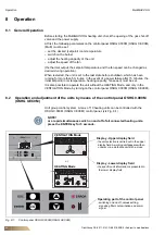
Page 43: ...pacity fan speed must be set It is also possible to operate the unit without the HEATING Mode and only in the VENTILATION Mode by turning on the control panel OSHG 0 000M OSHG 0 EC0M 8 2 Operation and adjustment of the units by means of the control panel OSHG 0 000M OSHG 0 EC0M Unit group control system A max of 10 heating units can be controlled with the OSHG 0 000M OSHG 0 EC0M control panel viz ...

Page 44: ...mation of selected menu positions The ESC key serves to conclude a menu selection or to return to the previous menu After pressing the key for longer than 5 sec the main menu appears Set the values within the menus with the setting keys Up Down for example to set the number of units desired temperature heating capacity selection of a unit the outside air rate position of the secondary louvre etc S...

Page 45: ...ETUP MENU X P T selection confirm selection ENTER or select unit into the next MENU back to ESC MENU SETUP Number of units set confirmation ENTER back to MENU SETUP ESC back to MENU SETUP select unit confirmation ENTER to the next MENU ESC back to MENU SETUP display selection ESC back to MENU SETUP select unit selection confirmation ENTER back to MENU SETUP temperature set confirmation ENTER to th...

Page 46: ...preselection Fan speed 1 Fan speed 2 Fan speed 3 0to 199 Pressure loss range Mode HEATING mode VENTILATION mode Supply air temperature only for supply air tempera ture control 1to 10 Number of the unit for which the supply air temperature is set 0to 70 Supply air temperature The unit number that was selected in the previous selection If the temperature difference is set Tset and less than 5 C is s...

Page 47: ...ches ON 1 OFF 0 X not used Symbol MENU MENU display on the control panel Setting possibilities Fig 8 3 Display of the HEATING MENU ESC lock press key for 3 sec settings setpoint temperature continue to the UNIT SELECT MENU ENTER ESC back to the MAIN MENU select unit confirm the selection ENTER and continue to the UNIT MENU ESC back to the UNIT SELECT MENU change values unit Confirm the selection a...

Page 48: ...ol Function Operation with fan speed 1 Operation with fan speed 2 Operation with fan speed 3 The adjusted heating capacity of the unit in the range 0 to 100 in 10 steps Display of the current heating capacity from 0 to 100 in 10 steps Incorrect range setting of the gas burner The unit is working with reduced heating capacity protecting the heat exchanger against overheating The unit is in run on m...

Page 49: ...eds 1 Fan speed 1 2 Fan speed 2 3 Fan speed 3 Setting the thermal output It is possible to set the thermal output from 0 to 100 in 10 steps 0 is the min thermal output of the unit 100 is the max thermal output of the unit With a supply air temperature control the symbol A is shown and the corresponding heating capacity thermal output is calculated automatically Adjustment of the outside air rate A...

Page 50: ...bol MENU MENU display on the control panel Setting possibilities Fig 8 4 Display of the VENTILATION MENU 1 2 3 4 5 6 7 8 9 10 1 1 2 3 4 5 6 7 8 9 10 1 1 1 100 1 or 1 1 1 1 ESC lock press key for 3 sec continue to the UNIT SELECT MENU ENTER ESC back to the MAIN MENU select unit confirm the selection ENTER and continue to the UNIT MENU ESC back to the UNIT SELECT MENU change values unit Confirm the ...

Page 51: ... key Symbol Function In order to cancel the key lock press the ESC key longer than 3 sec The specified unit functions faultlessly A fault has occurred at the specified unit or no data connection is available Symbol only VENTILATION MENU Symbol Function Fan switched off Operation with fan speed 1 Operation with fan speed 1 Operation with fan speed 3 Fault message of the gas burner Fault message of ...

Page 52: ...mbol MENU MENU display on the control panel Setting possibilities Setting the fan speeds 0 Fan switched off 1 Operation with fan speed 1 2 Operation with fan speed 1 3 Operation with fan speed 3 Adjustment of the outside air rate Adjustment of the outside air rate from 0 to 100 in 10 steps 0 recirculating air 100 outside air Increase of the outside air rate Decrease of the outside air rate Adjustm...

Page 53: ...he exhalation shutter unless the mixing chamber is on the unit or is controlled outside the Multi control The actuator with limit switches can be used for example to control the exhaust fans or other devices when reaching a certain mixing ratio The limit switch can be set so that when a certain position of the actuator set is reached the switch closes to com mand the exhaust fans to start 8 5 Diff...

Page 54: ...rk on the MultiMAXX unit heater please make sure that you statically discharge yourself before touching the printed circuit board and electrical components RISK OF BURNING Wait until the heat exchanger and the air handling unit cool down NOTE Observe regular intervals for inspection and repair for the maintenance of a unit heater Maintenance may only be carried by qualified specialists after the g...

Page 55: ... Multi Operation control panel is activated The filter insert should be exchanged When ordering the replacement filter please use the unit type code on page 3 Pos 1 Roof hood intake side Pos 2 G2 or G4 bag filter Remove the lateral screws screws with a plastic cap and open the upper part of the roof hood Remove the filter insert and replace it Close the roof hood and tighten the screws Fig 9 1 Fil...

Page 56: ... parts may be damaged dur ing cleaning Pos 1 Filter section Pos 2 Mat filter G2 or G4 Unlock the side panel of the filter section 1 by slightly turning quick action clamps by 90 and remove the filter Pull out the mat filter insert and replace it 2 Push the new mat filter insert into the filter chamber close the filter side part and secure it by turning the quick release fastener by 90 Fig 9 3 Repl...

Page 57: ...e manual fuse service necessary On the terminal box the phase is available on P1 but not on L1 Press the manual fuse service necessary The fan of the unit is running but supplies little air Air stream interrupted or limited filter con taminated Ensure free air passage Wrong rotation direction of fan Check the electrical connections only specialists Unit too noisy Air intake or discharge areas bloc...

Page 58: ...ng Explosions and fire can occur through escaped gas RISK OF BURNING Wait until the heat exchanger and the air handling unit cool down WARNING HAZARDOUS ROTATING COMPONENTS Wait to allow the fan rotational momentum to cease RECYCLING The disposal of the unit MultiMAXX HG or individual components must be carried out by an authorized appointed contractor with the necessary competence This appointed ...

Page 59: ... seller his rights concerning the liability for defects and after commissioning of the gas heating unit to the company which has carried out the commissioning and has confirmed this on the warranty certificate The warranty period is always extended by the time period from the assertion of claims for the right of elimination of defects until the time of their elimination possibly up to the time whe...

Page 60: ...pe and identification number of the MultiMAXX HG unit and the burner Warranty period 24 months Product MultiMAXX HG Identification number Type Burner Identification number Type The manufacturer guarantees that the unit was inspected and that this model conforms to all valid standards Stamp and signature The unit was installed by Date company stamp and signature The commissioning and warranty work ...

Page 61: ...MultiMAXX HG 62 FläktGroup DC 2011 0141 GB 2018 05 R5 Subject to modifications ...

Page 62: ... type HG serve for the heating ventilation or filtering of indoor or outdoor air They are installed in industrial warehouse retail and exhibition premises Declaration The machinery complies with all relevant provisions of Directives 2006 42 EC 2014 30 EU and 2014 35 EU List of harmonized standards applied in the conformity assessment EN ISO 14120 2015 EN ISO 13857 2008 EN ISO 12100 2010 EN ISO 112...

Page 63: ...accumulated industry experience The widest product range in the market and strong market presence in 65 countries worldwide guarantee that we are always by your side ready to deliver Excellence in Solutions PRODUCT FUNCTIONS BY FLÄKTGROUP Air Treatment Air Movement Air Diffusion Air Distribution Air Filtration Air Management Air Conditioning Heating Controls Service Learn more on www flaktgroup co...

Reviews: