Multi
MAXX
HG
Commissioning
FläktGroup DC-2011-0141-GB 2018-05/R5 • Subject to modifications
39
7.1.4.2 Setting the terminals on the Multi control board (HG ##.######.#M#)
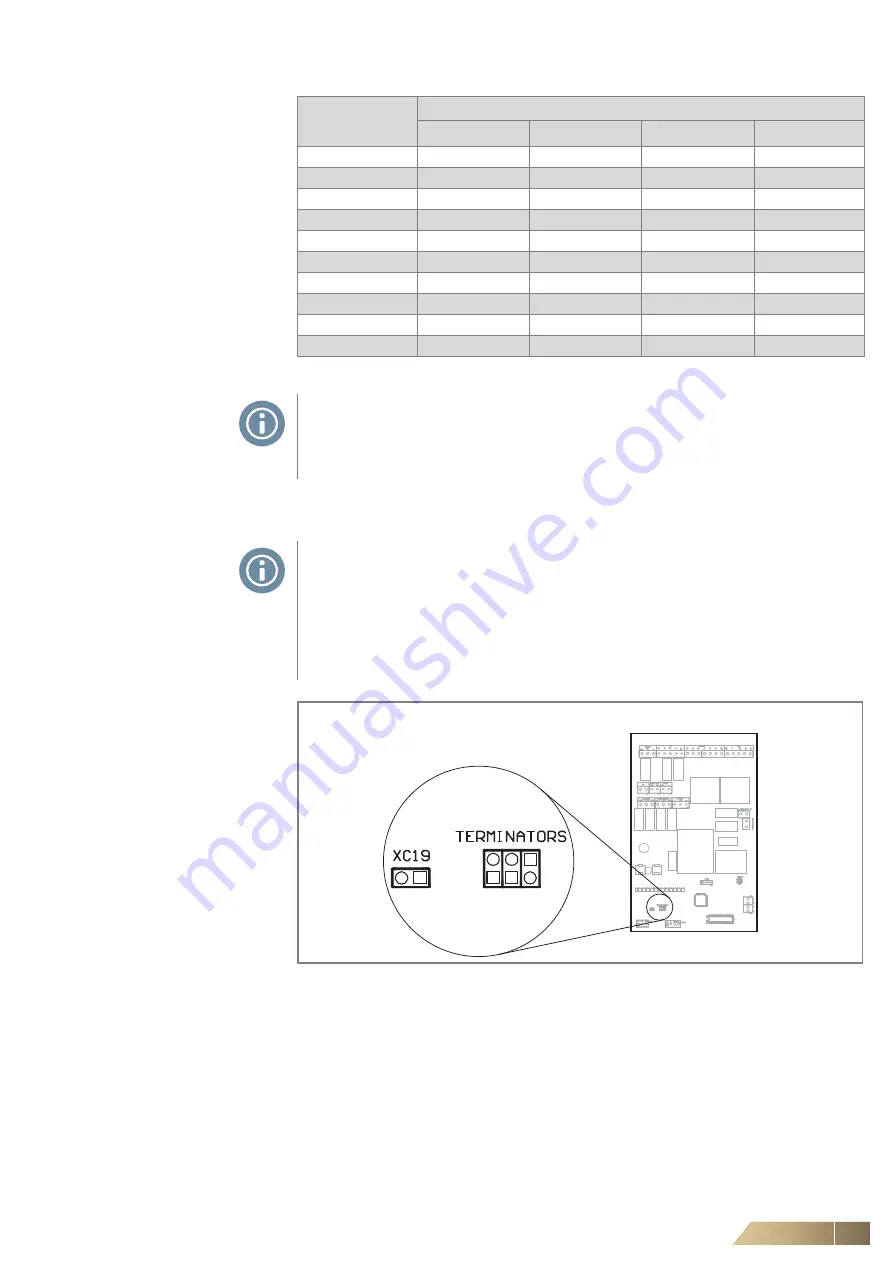
Fig. 7-4:
Terminal position
Unit number
Connection of the terminal pins and their combinations
Pins No. 12
Pins No. 11
Pins No. 10
Pins No. 9
1
0
0
0
0
2
0
0
0
1
3
0
0
1
0
4
0
0
1
1
5
0
1
0
0
6
0
1
0
1
7
0
1
1
0
8
0
1
1
1
9
1
0
0
0
10
1
0
0
1
Tab. 7-4:
Setting the unit addresses
NOTE!
Addressing (see Tab. 7-4) with switches 9 -12 (see Fig. 7-3) is required on each
control board located in the electrical box of the HG ##.######.#M# unit
(Multi control).
NOTE!
In the last electrical box of the HG ##. ######.#M# unit on the control board,
3 free TERMINATORS terminals must be connected (see Fig. 7-4).
For other control boards in electrical cabinets, these clamps must be left loose.
Terminal XC19 (Fig. 7-4) must be connected to the HG ##.######.#M# control box
OSHG 0.000M (OSHG 0.EC0M) of the HG ##.
For other control boards, it is necessary to leave this terminal free.
Control box Multi - HG ##.######.#M#


