background image

Roofmaster STEC non-insulated version - Installation and maintenance

3

FläktGroup DC_10082GB_20180213_R1

Specifications are subject to alteration without notice


3 TECHNICAL DESCRIPTION

The roof fan is used to generate required air flow at current pres-
sure drop equal to losses in the duct system. This is done using 
a rotating impeller inside the fan casing. 
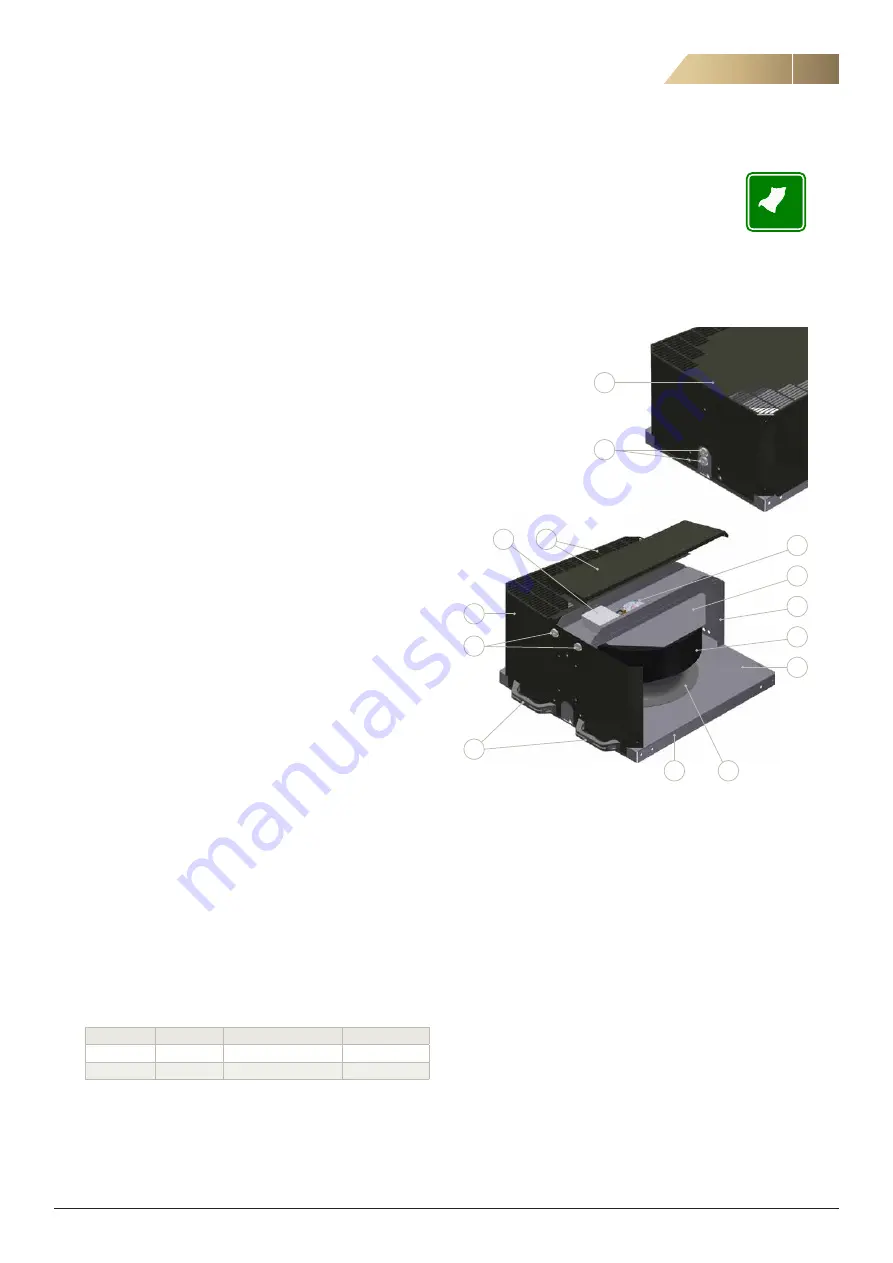
3.1 CONSTRUCTION 

1. Casing
2. Roof panel (1 or 3 pcs)
3. Bottom plate
4. Inlet cone
5. Impeller
6. Rain cover
7. Motor bracket
8. Motor
9. Junction box
10. Cable grommets
11. Handles (sizes 400 - 630)
12. Mounting frame with hinges (sizes 225 - 630)

3.2 APPLICATIONS

Roof fans are used as exhaust fans in ventilation systems.
The maximum allowed rotational speed for fan-motor combination 
is shown in the technical catalogue. 
Note!
If the fan is not used continuously in a cold climate, it is recom-
mended to use back draught shutter in the ducting. This prevents 
the humidity freezing within the fan structure.

3.3 MOTORS

Motors are either 1- or 3-phase external rotor EC motors with in-
tegrated impeller and speed controller.

Fan size

Motor type Motor construction

Input voltage

190 - 400

EC

External rotor

1~230 VAC

450 - 630

EC

External rotor

3~400 VAC

Detailed motor information as well as min. and max. allowed tem-
peratures are available in the technical catalogue.

2

1

3

5

7

6

8

1

4

10

10

11

2

SIZES 190 - 310

SIZES 355 - 630

9

Summary of Contents for Roofmaster STEC 190

Page 1: ...ROOF FAN ROOFMASTER STEC NON INSULATED VERSION INSTALLATION AND MAINTENANCE...

Page 2: ...y regulations Tools and protective equipment necessary for preventing accidents from occurring while installing and operating the fan must be used worn in accordance with the local safety regulations...

Page 3: ...225 630 3 2 APPLICATIONS Roof fans are used as exhaust fans in ventilation systems The maximum allowed rotational speed for fan motor combination is shown in the technical catalogue Note If the fan i...

Page 4: ...WEIGHTS Htot W1 W2 245 W3 1112 775 853 W5 1069 775853 W5 12 12 W4 Fan size W1 W2 W3 W4 W5 Htot Weight kg 190 358 348 1 130 8 225 467 469 442 398 368 234 10 310 467 469 442 398 368 314 16 355 577 579...

Page 5: ...he product 4 2 TRANSPORT SAFETY The transport material is to be selected according to the packag ing and the weight of the product Loading must be carried out as instructed 4 3 INTERMEDIATE STORAGE If...

Page 6: ...3 Place the mounting frame on the base frame roof curb and fasten it with bolts If the base frame is made of concrete use anchor bolts There are four 12 mm holes eight 12 mm in size 630 for bolts in t...

Page 7: ...In case of electrical accessories all required instructions are in cluded in the delivery 5 4 1 THE FAN WITH SAFETY SWITCH INSTALLED AT THE COMMISSIONING PHASE 1 Fasten the safety switch in proper pl...

Page 8: ...roof fan does not need any special service However it is necessary to clean the fan impeller especially when the air is not clean This helps to avoid vibrations in the impeller If there is an abnorma...

Page 9: ...ff the fan from the isolator and wait 5 minutes before starting the maintenance work 2 Open the fixing bolts after that the fan casing can be lifted open The fan shall be locked to open position with...

Page 10: ...from the base frame 7 Remove the motor bolts if necessary protect motorized impel ler from dropping down and lift the motor bracket away 8 Remove the inlet cone fastened with pop rivets and sealing c...

Page 11: ...th integrated controller is in accordance with the Machinery Directive 2006 42 EC And that the machinery is in conformity with the provisions of the following other Directives EMC Directive2014 30 EU...

Page 12: ...y application area We offer our customers innovative technologies high quality and outstanding performance supported by more than a century of accumulated industry experience The widest product range...

Reviews: