background image

 Roofmaster STEC non-insulated version - Installation and maintenance

6

FläktGroup DC_10082GB_20180213_R1

Specifications are subject to alteration without notice


5 INSTALLATION

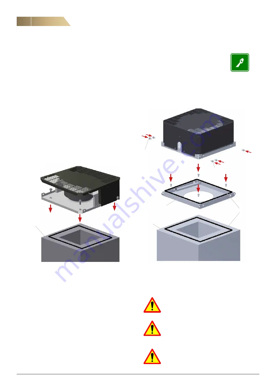
5.1 FAN INSTALLATION

The fan can be installed on a roof curb or directly on a base 
frame (size 190), or by using a mounting frame (included in deliv-
ery, sizes 225…630).

5.1.1 SIZE 190

1.  Fasten the sealing tape (included in delivery) to the base 

frame/roof curb or to the bottom plate of the fan.

2.  Place the fan on the base frame/roof curb and fasten it 

through the bottom plate with four bolts. If the base frame is 
made of concrete use anchor bolts. There are four Ø12 mm 
holes for screws in the bottom plate. Holes can be accessed 
by removing the roof panel or the entire outer casing by loos-
ening screws or M6 bolts on both sides of the fan.

5.1.2 SIZES 225 - 630

1.  Detach the mounting frame from the fan (M8 bolts on both 

sides of the fan).

2.  Fasten the sealing tape (included in delivery) to the base 

frame/roof curb or to the bottom of the mounting frame.

3.  Place the mounting frame on the base frame/roof curb and 

fasten it with bolts. If the base frame is made of concrete, use 
anchor bolts. There are four Ø12 mm holes (eight Ø12 mm in 
size 630) for bolts in the mounting frame.

Note that:

-  Possible wind load and hinges can generate high loads to the 

fastenings.

-  Safety switch and cable grommet shall be on the same side of 

the fan. This defines also the position of the hinges. 

5.2 SAFETY INSTRUCTIONS

The fan fulfills the requirements of the CE marking defined in 
the Machinery Directive. The fan must be installed following the 
standard EN 292/294.


The electrical installations should only be carried out 

by authorized personnel.

Switch off the power and wait 5 minutes before start-

ing the installation or maintenance work. Be sure that 

the fan cannot be started unexpectedly while work in 

progress.

The fan delivery does not include any inlet guard. If 

the installation method requires, inlet opening must 

be protected.

4.  Fasten the sealing tape (included in delivery) to the upper part 

of the mounting frame.

5.  Fasten the fan to the mounting frame with M8 bolts.

Base frame or

roof curb BOGA

Hinge bolt

Hinge bolt

Mounting frame

(included in delivery)

Sealing

Base frame or

roof curb BOGA

Summary of Contents for Roofmaster STEC 190

Page 1: ...ROOF FAN ROOFMASTER STEC NON INSULATED VERSION INSTALLATION AND MAINTENANCE...

Page 2: ...y regulations Tools and protective equipment necessary for preventing accidents from occurring while installing and operating the fan must be used worn in accordance with the local safety regulations...

Page 3: ...225 630 3 2 APPLICATIONS Roof fans are used as exhaust fans in ventilation systems The maximum allowed rotational speed for fan motor combination is shown in the technical catalogue Note If the fan i...

Page 4: ...WEIGHTS Htot W1 W2 245 W3 1112 775 853 W5 1069 775853 W5 12 12 W4 Fan size W1 W2 W3 W4 W5 Htot Weight kg 190 358 348 1 130 8 225 467 469 442 398 368 234 10 310 467 469 442 398 368 314 16 355 577 579...

Page 5: ...he product 4 2 TRANSPORT SAFETY The transport material is to be selected according to the packag ing and the weight of the product Loading must be carried out as instructed 4 3 INTERMEDIATE STORAGE If...

Page 6: ...3 Place the mounting frame on the base frame roof curb and fasten it with bolts If the base frame is made of concrete use anchor bolts There are four 12 mm holes eight 12 mm in size 630 for bolts in t...

Page 7: ...In case of electrical accessories all required instructions are in cluded in the delivery 5 4 1 THE FAN WITH SAFETY SWITCH INSTALLED AT THE COMMISSIONING PHASE 1 Fasten the safety switch in proper pl...

Page 8: ...roof fan does not need any special service However it is necessary to clean the fan impeller especially when the air is not clean This helps to avoid vibrations in the impeller If there is an abnorma...

Page 9: ...ff the fan from the isolator and wait 5 minutes before starting the maintenance work 2 Open the fixing bolts after that the fan casing can be lifted open The fan shall be locked to open position with...

Page 10: ...from the base frame 7 Remove the motor bolts if necessary protect motorized impel ler from dropping down and lift the motor bracket away 8 Remove the inlet cone fastened with pop rivets and sealing c...

Page 11: ...th integrated controller is in accordance with the Machinery Directive 2006 42 EC And that the machinery is in conformity with the provisions of the following other Directives EMC Directive2014 30 EU...

Page 12: ...y application area We offer our customers innovative technologies high quality and outstanding performance supported by more than a century of accumulated industry experience The widest product range...

Reviews: