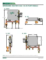
11
OWNER’S MANUAL
NEUTON™
2-10 VDC
24~
COM
Belimo
TR24-SR-T US
HWR
FROM CHILLED
BEAM LOOP
Belimo
TR24-SR US
CWR
CWS
HWS
COM 24~ 2-10 VDC
P/T
Port
P/T
Port
ISO VLV
UNION
UNION
ISO VLV
CHECK
VALVE
CHECK
VALVE
PUMP
TO CHILLED
BEAM LOOP
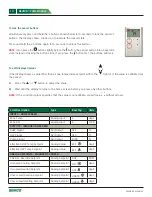
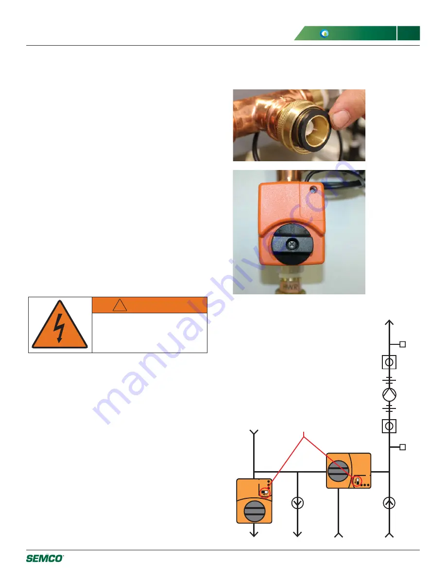
Rotation Direction
Switches
venting is complete .
Venting the Pump
Venting the pump prior to operation ensures that all air
is out of the pump rotor can, and the back bearings are
lubricated with water . The pump is vented by rotating the
center screw on the pump a single turn counterclockwise
(See
Figure 11
on page 25) and allowing a drop of water
to escape . Tighten the vent screw when complete .
Electrical Wiring
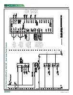
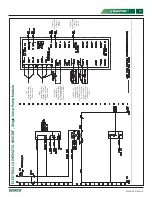
Make electrical connections as shown in the appropriate
electrical schematic for your configuration rung 103 (See
pages 12-13) .
Power Requirements:
• Voltage: 208-230/1/60
• Amp Draw: 1 .2 FLA
!
WARNING
ELECTRIC WIRING MUST
BE CARRIED OUT BY A
QUALIFIED ELECTRICIAN.
Controls Wiring
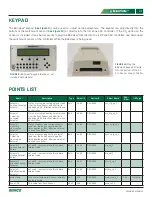
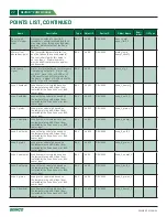
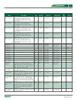
The controller RS-485 communication ports accepts a 2
conductor plus shield connection for BACnet MS/TP, N2,
or Modbus communications . ARC156 is also available .
6)
A wall mount zone sensor is shipped loose for
mounting in the space . The communicating sensor
requires a four conductor cable . Wire the ZS Pro
Zone Sensor in the chilled beam zone to the I/O
Zone 583 Controller per electrical schematic rungs
129-132 .
7)
Connect the BACview
6
(optional) .
8)
Connect the start/stop contacts (optional) or jumper
at terminals 1370 and 1371 .
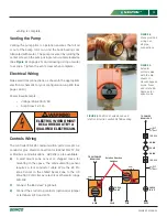
FIGURE 4.
Place provided
o-rings on
all pipe
connections .
FIGURE 5.
Actuator
control valve
with the dial
shown in
closed/bypass
mode . Press
and rotate 90
degrees for
open mode .
FIGURE 6.
Position of valve knob and
rotation direction switch AFTER venting .

