FlameStop FDCIE Panels With AS4428.3-2010 Fascia
Installation and Operation Manual
Page 25
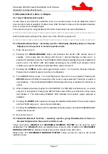
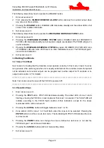
3.5.3 Setting Delay Time of Alarm Output
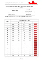
Delay time of alarm output can be set through the following steps.
1
Enter access level III.
2
Set the “3” of SW2 (
ALARM OUTPUT
) to ON position.
3 Pressing
the
OUTPUT PROGRAM
button, the
OUTPUT PROGRAM
LED illuminates steadily
and
ALARM OUTPUT FAULT
LED flashes to show the FDCIE enters delay time setup. The
FAULT
LED will indicate according to the FDCIE fault condition. Other indicators, except for
the above mentioned LEDs, will be turned off.
4 The Dip switches “1” to “4” of SW3 (
DELAY TIME
) are used for setting the delay time of the
selected Sounder Output from 0-150 seconds, refer to Table 3-8.
5 Pressing
the
ENTER
button saves the current setting. The FDCIE will sound for 1 second to
indicate the successful setup.
6 Pressing
the
CANCEL
button will exit alarm output delay time setup and the
OUTPUT
PROGRAM
LED will be turn off.
7
Set the “3” of SW2 (
ALARM OUTPUT
) and “1” to “4” of SW3 (DELAY TIME) to OFF position.
8
Exit access level III.
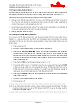
3.5.4 Sounder Output Mode
Instead of all of the sounder outputs activating at the same time you are able to program certain
sounder outputs to activate when a particular zone/s are activated. This type of programming is
rarely used. Default setting is Immediate Output. Please refer to the below table (3-6) when for
additional information.
Table 3-6
Mode Description
DISABLE/ENABLE
LED
TEST
LED
1 No
output
OFF
OFF
2
Output after alarm output activated
OFF
ON
3
Delay output (refer table 3-8 to set time)
ON
OFF
4
Immediate output (Default)
ON
ON


