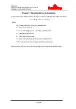
PFS200-2
Intelligent FDCIE With AS4428.3-2010 Fascia
Installation and Operation Manual
Page 38
In this screen, the SOUNDER CIRCUIT OUTPUT on the loop interface board can be disabled or
enabled.
6.3.4.4 Disabling/Enabling Delays
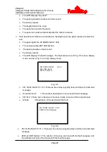
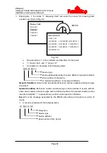
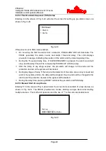
Inputting number 4 in the screen shown in Fig. 6-14 can enter the screen of disabling/enabling
delays, as shown in Fig. 6-22.
Fig. 6-22
In the above screen, you can operate as follows:
Selecting number 1 will disable all delay settings in the system.
Selecting number 2 will enable system to output according to the pre-set delay time, and
light
DELAY MODE
LED.
Note: If the fire alarm is from a manual call point, then the system will output immediately
despite any delay settings.
6.3.4.5 Deleting Disabled Information in Network
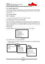
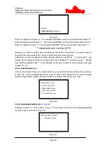
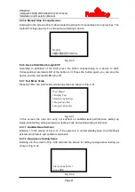
Entering number 5 in the screen of Fig. 6-14 will enter the screen for deleting disabled
information in network, as shown in Fig. 6-23.
Fig. 6-23
In the above screen, entering the number of the message, and pressing
ENTER
to confirm will
delete the disabled information from network FDCIE.
6.3.5 User Mode
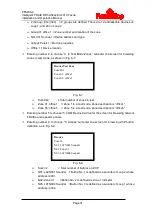
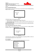
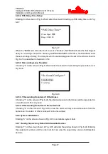
Pressing
MODE
button can enter user mode setup screen as shown in Fig. 6-24.
Fig. 6-24
* Delay Mode*
1.
Disable
2.
Enable
Delete Net Disable
Num: 000
*User Mode*
1 LCD Contrast
2
Browse Mode
3 Print Mode
4 PAS Setup
5 Start Devices
6 Stop Devices

