PFSIFP8
Intelligent Fire Alarm Control Panel
Installation and Operation Manual
Page 9
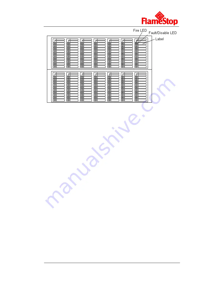
Fig. 3-4
On the indication panel, each unit consists of two indicators and a label. The user can
put the name of device on the right of the indicators.
Fire LED:
Red. It illuminates when a fire occurs in a zone. It goes out after the
FACP is reset.
Fault/Disable LED:
Yellow. It flashes when there is any fault with the zone. If
all devices in this zone have been disabled, the LED illuminates steadily. It
goes out after the fault conditions are cleared or the FACP is reset.
The two indication boards appear the same, but on their internal circuit boards,
there is a pin XS2 respectively. If this pin on any of the two panels is not shorted by
a jumper, then this panel will be numbered as No. 1 with fixed LED numbers
ranging from 1 to 70, and the pin XS2 on the other one could be shorted so that the
panel is numbered No. 2 with fixed LED numbers from 71 to 140.
3.2 Components
3.2.1 Standard Components
A standard FACP consists of mother board, main board, loop board, power supply,
indication board, and zone indication panel.
Mother Board:
The mother board is installed on the back of the FACP, which connects with power
supply board through cables, with switch board through data cable. It connects with
and powers the main board, loop board, network board and communication board
through slots. It also provides input/output terminals.
Main board
Main board is the core of the FACP, which contains CPU and interfaces to other
main and optional components of the system. It also has fire alarm and fault output
ports.
Summary of Contents for PFSIFP8
Page 1: ......


