background image


PFSIFP8 

Intelligent Fire Alarm Control Panel                


Installation and Operation Manual


Page 18  

4.4.3.5  Connection of Communication Loop 


Fig. 4-8 

4.5 Connection Inspection and Device Registration 

4.5.1 Connection Inspection 

Check the circuit connected with the FACP. Measure the insulation resistance between 
loops and between loops and ground, which should be more than 20M

.  Measure the 

load of detection loops, which should be more than 1k

. The resistance between cables 

of ALARM ROUTING, OUTPUT TO SOUNDER and OUTPUT TO FPE should be equal 
to the end-of-line resistance. 

4.5.2 Device Registration  

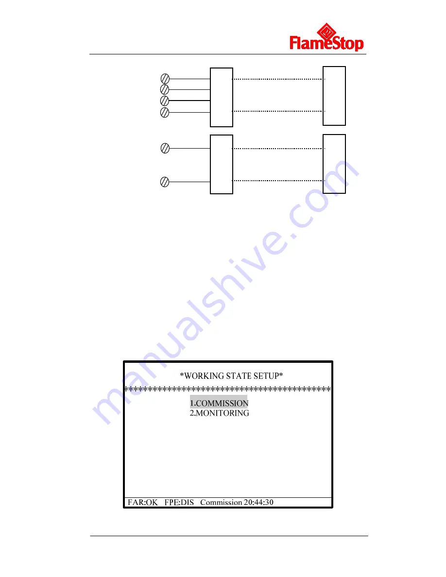
Step 1: Set the FACP into commission state. Press 

SYSTEM SETUP

 and enter system 

setup menu.  Choose “3 WORKING STATE SETUP”, you can then set the FACP as  
commission or monitoring state (Fig. 4-9).  


Fig. 4-9 

O+ 
O- 
I+ 
I- 

Maximum 32 FACPs 

Maximum 64 repeater panels 

Network 

(Any loop)   

Repeater 

Repeat

er Panel 

Repeat

er Panel 

FACP 

FACP 

Summary of Contents for PFSIFP8

Page 1: ......

Page 2: ...ction and Components 6 3 1 Exterior and Interior Construction 6 3 1 1 Display Area 7 3 1 2 Description of LEDs 7 3 1 3 Description of Keys 8 3 1 4 Zone Indication Panel 8 3 2 Components 9 3 2 1 Standa...

Page 3: ...of System Operation 26 6 1 Keypad 26 6 1 1 Keypad Functions 26 6 1 2 Methods of Data Input 26 6 1 3 Unlocking and Locking the Keypad 26 6 2 User Operation Instruction Operator Password Required 27 6 2...

Page 4: ...Consult with the appropriate Authority Having Jurisdiction AHJ for confirmation of the requirements PFSIFP8 Fire Alarm Control Panel FACP shall only be installed and serviced by a trained specialist...

Page 5: ...ints 9 5 Output to fire alarm devices 7 8 Control of fire alarm routing equipment 7 9 Outputs Output to fire protection equipment 7 10 The power supply of the PFSIFP8 FACP complies with AS 7240 4 requ...

Page 6: ...xed temperature heat detector PHI 9103 complying with AS 7240 5 photoelectric smoke detector PHI 9102 complying with AS 7240 7 intelligent manual call point PXI 9202 complying with AS 7240 11 intellig...

Page 7: ...nnecting with up to 32 network FACPs Recommended Wiring subject to local installation codes FireCable 2E 1 0 2 core and Earth 1mm2 CSA Pirelli Cable Limited FP200 FLEX 2 core and Earth 1mm2 CSA Recomm...

Page 8: ...e Length 1000m 2 5 Output Loop Parameters Recommended Wiring subject to local installation codes FireCable 2E 1 0 2 core and Earth 1mm2 CSA Pirelli Cable Limited FP200 FLEX 2 core and Earth 1mm2 CSA R...

Page 9: ...and interior construction are shown in Fig 3 1 and 3 2 1 2 3 4 5 6 7 8 9 0 F1 F2 F3 1 2 3 5 4 484mm 850mm 191mm Fig 3 1 1 LCD 2 Indicators 3 Keypad 4 Zone indication board 5 Printer 1 2 3 4 5 6 7 8 9...

Page 10: ...out when the pre alarm is cleared Battery Fault Yellow It illuminates when standby power is in fault After the fault is cleared it will go out Verify Yellow It illuminates when the FACP is in Stage 2...

Page 11: ...ent and command equations for modifying device type for setting the shift time of day night mode for setting operation mode for system initialization USER SETUP User set up key operator password requi...

Page 12: ...wo panels is not shorted by a jumper then this panel will be numbered as No 1 with fixed LED numbers ranging from 1 to 70 and the pin XS2 on the other one could be shorted so that the panel is numbere...

Page 13: ...cator on the right top and the exit with paper cutter The printing head is installed inside the frame and the paper insert scoop is at its bottom The printer is fixed onto the front panel by the sprin...

Page 14: ...call point such as PXI 9202 can be connected to the loop of PFSIFP8 When fire is confirmed manually press the glass on the MCP alarm signal can be sent to the FACP After receiving the alarm signal the...

Page 15: ...heck the packing list according to engineering requirement The main items to be examined are installation and operation manual key to the FACP and etc Check Internal Components and Interconnection ins...

Page 16: ...illuminated Check if the LEDs showing the state of system can be illuminated one by one Check if the LEDs showing the device state in zone indication panel are illuminated in turn Check if the buzzer...

Page 17: ...the batteries according to Fig 4 2b and then connect with the battery terminal BAT power board BAT power board Fig 4 2b Note Do not make the final battery connections until the installation is comple...

Page 18: ...y the isolators will not be lost in case of short or open circuit with the loop and the FACP reports loop fault OUTPUT TO FPE It outputs according to settings in Section 6 3 2 when there is fire alarm...

Page 19: ...tion Connect the loop in correct polarity and add the resistor to the end of the line NOTE The sounder strobes are polarity sensitive Note polarity in connection The maximum current of the circuit dep...

Page 20: ...tion The maximum current of the circuit depends on the number of fire supervisory device Do not overload 4 4 3 4 Connection of Class A Loops A Class A loop is shown in Fig 4 7 Fig 4 7 Note If more tha...

Page 21: ...more than 20M Measure the load of detection loops which should be more than 1k The resistance between cables of ALARM ROUTING OUTPUT TO SOUNDER and OUTPUT TO FPE should be equal to the end of line res...

Page 22: ...1 Defining Tool through a PC and download the definitions to the FACP Refer to Def2 1 Defining Tool User s Manual for detailed operation 4 7 Field Device Commission After connection definition and dow...

Page 23: ...ormal standby state The system will display properly if it is in normal state otherwise it will display abnormal information 5 1 Normal Information The normal display is shown in Fig 5 1 which means t...

Page 24: ...20 44 30 Press ACK to acknowledge Press F1 to start Zone sounder Press F2 to start Local output Press ENTER to view detail Press L R scroll to switch inf type 001 May 07 09 20 Zone001 Sum002 032 Room...

Page 25: ...n case of a pre alarm the Pre Alarm LED will illuminate and the buzzer of the FACP will sound continuously 5 3 1 Display of Pre alarm Fig 5 4 5 3 2 Disposal of Pre alarm FAR OK FPE DIS Commission 20 4...

Page 26: ...he pre alarm will be automatically cancelled If the condition is met the pre alarm will automatically change to a fire alarm 5 3 2 2 Disposal of Pre alarm Message in Day Mode In day mode if a pre alar...

Page 27: ...to be cleared by pressing RESET key after the fault is removed Fault relay outputs Keypad fault The panel reports keypad fault if its keypad circuit is in fault It lights the FAULT and SYSTEM FAULT L...

Page 28: ...following order fire alarm pre alarm supervisory fault disable 1 The earliest fire alarm is displayed in priority The latest pre alarm supervisory fault and disabled message are displayed in priority...

Page 29: ...e into its running log If the fire alarm fault or supervisory information still exists after reset operation the system will display corresponding states Otherwise it returns to normal operation state...

Page 30: ...2 User Operation Instruction Operator Password Required Pressing USER SETUP in normal standby state and entering operator password will enter user setup menu Fig 6 1 6 2 1 Browsing messages Choosing 1...

Page 31: ...t the highlighted item by choosing or You can view details of this item by choosing ENTER or exit by choosing CANCEL 6 2 1 1 Browsing Detection Points Choosing 1 on the screen shown in Fig 6 2 will en...

Page 32: ...groups as in Fig 6 5 Fig 6 5 6 2 1 4 Browsing Repeated Codes Choosing 4 on the screen shown in Fig 6 2 will enter the screen for browsing repeated codes as in Fig 6 6 FAR OK FPE DIS Commission 20 44 3...

Page 33: ...d Command Equations Choosing 6 on the screen shown in Fig 6 2 will enter the screen for browsing the event and command equations as in Fig 6 8 FAR OK FPE DIS Commission 20 44 30 BROWSE EVENT COMMAND E...

Page 34: ...20 44 30 HISTORY LOG 1 FIRE HISTORY 2 COMMON HISTORY 3 INITIALIZATION Fig 6 9 The log of fire alarm common history information and initialization can be browsed under this menu If the printer is set i...

Page 35: ...er the screen for printer setup as in Fig 6 11 On this screen 1 means printing is disabled 2 means only fire alarm messages are to be printed and 3 means history log being browsed can be printed out b...

Page 36: ...the FACP enters day mode or night mode according to the pre set start stop time If when the FACP works in day mode alarm dependency Type A or Type B is set and the condition for dependency is not met...

Page 37: ...EST 3 ALARM ROUTING TEST Fig 6 15 Choosing 3 on the screen of Fig 6 14 the FACP will enter the screen for setting up zones for testing as shown in Fig 6 16 where the zone number to test and the testin...

Page 38: ...ne will be automatically cleared 6 2 7 Start Stop Choosing 7 on the screen of Fig 6 1 will enter the screen for starting or stopping addressable devices Fig 6 17 Fig 6 17 6 2 8 Disable Enable Choosing...

Page 39: ...tion on addressable devices will be demonstrated as an example FAR OK FPE DIS Commission 20 44 30 DISABLE ENABLE 1 DIS ENABLE DEVICE 2 DIS ENABLE ZONE Fig 6 18 Choosing 1 on the screen in Fig 6 18 ent...

Page 40: ...20 44 30 SYSTEM SETUP 1 PROGRAMMING 2 LOCAL OUTPUT SETUP 3 WORKING STATE SETUP 4 DEVICE DEBUG Fig 6 20 6 3 1 System Resource Setup Choosing 1 on the screen of Fig 6 20 the FACP enters the menu for se...

Page 41: ...in Fig 6 23 below FAR OK FPE DIS Commission 20 44 30 POINT SETUP Zone 1 999 001 Device Type 01 OPTICAL SMOKE Attribute 0 6 1 Text 40 Byte Loop 01 Point 1 242 001 Fig 6 23 Choosing ENTER after program...

Page 42: ...t as Type B dependency the alarm of a detector from this zone will be reported as a pre alarm and when there is another detector alarm from any zone the FACP will report a fire alarm Sounder mode setu...

Page 43: ...e Choosing 4 on the screen of Fig 6 21 will enter the screen for setting start and stop time of day mode If delay mode is enabled the system will automatically enter delay mode in during day time and...

Page 44: ...and command E C setup for creating modifying deleting and initializing events and commands FAR OK FPE DIS Commission 20 44 30 EVENT COMMAND SETUP 1 CREATE 2 MODIFY 3 DELETE 4 INITIALIZATION Fig 6 28...

Page 45: ...lational operators and x in which refers to or and x refers to and 5 The delay time for devices to be activated can be 0s to 99s which can appear in the equation as numbers from 00 to 99 6 Wildcard ch...

Page 46: ...3 1 6 5 Initializing E C Equations Choosing 4 in the screen of Fig 6 28 and entering super password on prompt will delete all E C equations 6 3 1 7 Device Type Setup Choosing 7 on the screen of Fig 6...

Page 47: ...ggered on fire alarm signals from more than 1 device which may be from different zones 2 Output will be triggered on E C setup The delay time cannot be set for F P E A which would always output immedi...

Page 48: ...DEVICE LEARN 2 REPEATED POINTS CHECK 3 MODIFY ORIGINAL CODE 4 MODIFY POINT SENSITIVE 5 PULSE MODE DEBUG 6 DIGITAL MODEDEBUG 7 SYSTEM INITIALIZATION Fig 6 32 Choosing 3 in the above screen will access...

Page 49: ...PFSIFP8 Intelligent Fire Alarm Control Panel Installation and Operation Manual Page 46 Fig 6 34 Choose 6 on the screen of Fig 6 32 for digital method debug as in Fig 6 35 Fig 6 35...

Page 50: ...is the quiescent current when the FACP is with no load ILmax 2 4A is the maximum loop current IFout 0 5A 3 1 5A which is the alarm output current The FACP provides 3 fire alarm outputs output current...

Page 51: ...2 Display AC Fault after power up No AC power Check and connect AC wire 3 Display Battery Fault after power up a Loose connection with battery b Battery discharged or damaged a Open the power box and...

Page 52: ...5V XP1 XP1 27V GND BAT BAT 5V GND GND 24V TX RX 5V GND XT5 XT2 XT6 XT3 AC1 AC2 L G N 5V GND V V 1 2 3 4 5 7 8 6 9 10 13 11 12 XS1 5V GND GND 24V TX RX 13 14 B1 Lining Board Earth Stud Cabinet Earth St...

Page 53: ...ER DEFINED 15 USER DEFINED 16 USER DEFINED 17 USER DEFINED 18 USER DEFINED 19 USER DEFINED Fire Alarm Signal Input Signal 20 USER DEFINED 21 SUPERVISORY 22 WATERFLOW 23 USER DEFINED 24 USER DEFINED 25...

Page 54: ...INED 53 USER DEFINED 54 USER DEFINED 55 USER DEFINED 56 USER DEFINED 57 USER DEFINED 58 USER DEFINED 59 USER DEFINED 60 USER DEFINED 61 AC Power 62 Battery 63 Ground F 64 SounderA 65 F P E A 66 ALARM...

Page 55: ...OWSE ZONES BROWSE GROUPS BROWSE REPEAT CODE BROWSE PANEL STATUS BROWSE EVENT COMMAND BROWSE LOG CLOCK PRINTER SETUP DISABLE Only Fire All History DELAY MODE Disable Enable ACKNOWLEDGE TIMER TEST MODE...

Page 56: ...TUP ZONE SETUP COMMUNICATION SETUP DAY NIGHT TIME SETUP MODIFY PASSWORD EVENT COMMAND SETUP DEVICETYPE SETUP LOCAL OUTPUT SETUP WORKING STATE SETUP COMMISSION MONITORING DEVICE DEBUG DEVICE LEARN REPE...

Page 57: ...Flamestop Australia Pty Ltd 1 70 GIBBES STREET CHATSWOOD NSW 2067 PH 02 9932 2020 FAX 02 9932 2022 sales flamestop com au...

Reviews: