PFSIFP8
Intelligent Fire Alarm Control Panel
Installation and Operation Manual
Page 49
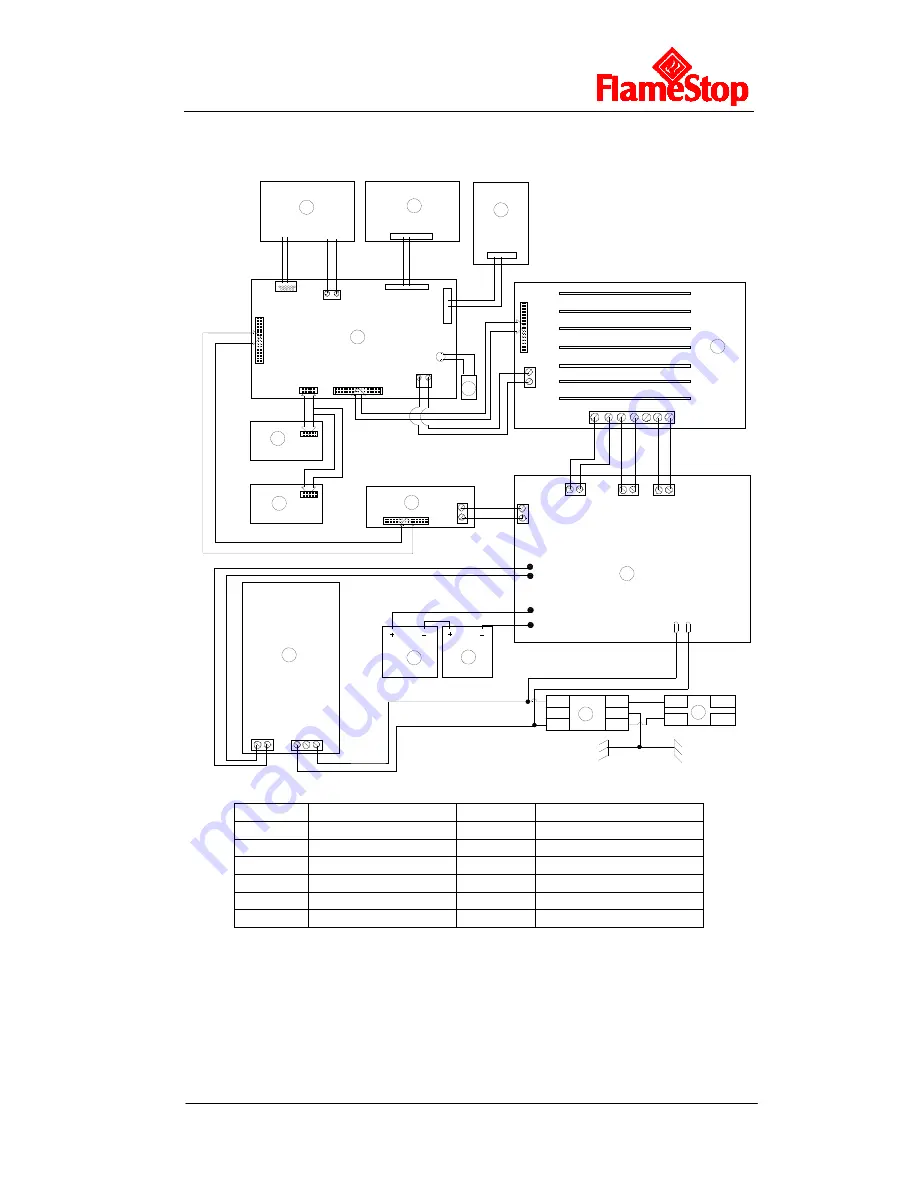
Appendix 1 Internal Connection Diagram
G
N
L
G
N
L
N
L
N
L
XS1
XS4
G
5V
XS7
XS9
XS6
XS8
G 5V
XS5
XS1
XS3
XT20
XT15
XS15
XT
1
6
GND
5V
XP1
XP1
2
7
V
G
N
D
BA
T
+
BAT
-
5V
GND
GND
24V
TX RX
5V
GN
D
XT5
XT2
XT6
XT
3
AC1
AC2
L
G
N
5V
GN
D
V+ V-
1
2
3
4
5
7
8
6
9
10
13
11
12
XS1
5V
GND
GND
24V
TX RX
13
14
B1
Lining Board
Earth Stud
Cabinet
Earth Stud
1
LCD 2
Keypad
Board
3
LED Board
4
Switch Board
5
Mother Board
6
Zone Indication Board 1
7
Zone Indication Board 2
8
Printer
9
AC/DC Power Module
10
Power Supply Board
11
Filter 12
Air
Switch
13
Battery 14
Buzzer
Summary of Contents for PFSIFP8
Page 1: ......


