VESDA-E VEP-A00-P Product Guide
www.xtralis.com
33
4.3
Wiring
The screw type terminals located on electrical terminals within the VEP-A00 detector will accept wire sizes
from 0.2 mm² to 2.5 mm² (24 – 14 AWG).
Refer to Codes and Standards Information for Air Sampling Smoke Detection on page iii for code specific
requirements.
Refer to the VESDA-E System Design Manual for cabling details.
Note:
The VEP-A00 detector is IP 40 rated, therefore a suitable cable gland or conduit must be used to
maintain the IP rating. (The IP rating is not UL tested.)
Caution:
Electrostatic discharge (ESD) precautions need to be taken prior to removing the fascia from
the detector in order to prevent damage to sensitive electronic components within the VEP-A00.
Attention :
Les precausions contre le decharge electrostatique dois etre respecter avant d’ouvrir le panneau
du detecteur afin de prevenir au dommage des composants electroniques a l’interieur du VEP-
A00.
4.3.1
Cabling Inlets
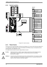
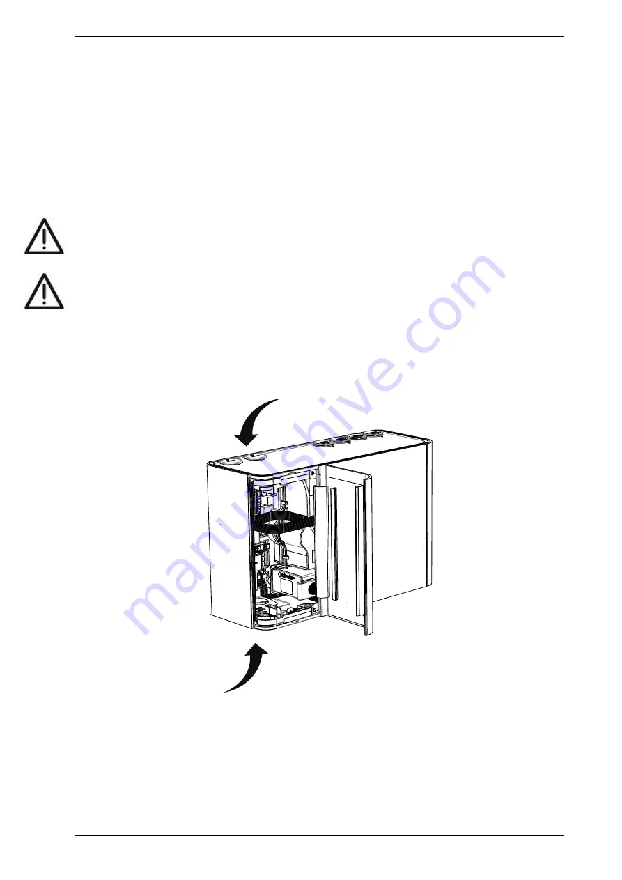
The VESDA-E VEP-A00 contains four inlets for power, relay and network cabling, located on the upper and
lower sides of the detector base. The holes have a diameter of 26 mm (1.02 inch).
Note:
To maintain the specified IP rating, cable glands or conduit must be used.
Figure 4-32: Cabling Inlets
Summary of Contents for VESDA-E VEP-A00-1P
Page 2: ......
Page 10: ...VESDA E VEP A00 P Product Guide 4 www xtralis com This page is intentionally left blank ...
Page 20: ...VESDA E VEP A00 P Product Guide 14 www xtralis com This page is intentionally left blank ...
Page 52: ...VESDA E VEP A00 P Product Guide 46 www xtralis com This page is intentionally left blank ...
Page 80: ...VESDA E VEP A00 P Product Guide 74 www xtralis com This page is intentionally left blank ...
Page 106: ...VESDA E VEP A00 P Product Guide 100 www xtralis com This page is intentionally left blank ...
Page 112: ...VESDA E VEP A00 P Product Guide 106 www xtralis com Z zone 56 58 77 101 ...


