29 |
P a g e
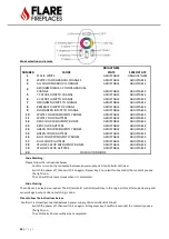
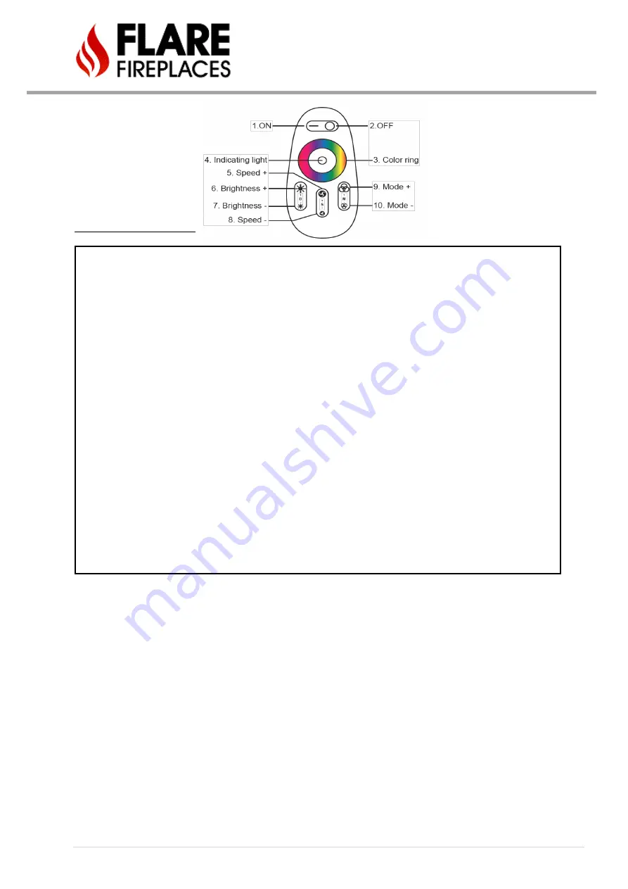
Mode selection and remote
NUMBER
MODE
BRIGHTNESS
STATE
SPEED STATE
1
STATIC WHITE
ADJUSTABLE
UNADJUSTABLE
2
WHITE COLOR GRADUAL CHANGES
ADJUSTABLE
ADJUSTABLE
3
ALL COLORS GRADUAL CHANGES
ADJUSTABLE
ADJUSTABLE
4
RED/GREEN/BLUE 3 COLORS GRADUAL
CHANGE
ADJUSTABLE
ADJUSTABLE
5
7 COLORS JUMP TO CHANGE
ADJUSTABLE
ADJUSTABLE
6
3 COLORS JUMP TO CHANGE
ADJUSTABLE
ADJUSTABLE
7
RED/GREEN JUMPS TO CHANGE
ADJUSTABLE
ADJUSTABLE
8
REB/BLUE JUMPS TO CHANGE
ADJUSTABLE
ADJUSTABLE
9
BLUE/GREEN JUMPS TO CHANGE
ADJUSTABLE
ADJUSTABLE
10
WHITE COLOR FREQUENTLY BLINKS
ADJUSTABLE
ADJUSTABLE
11
WHITE COLOR GLITTERS
ADJUSTABLE
ADJUSTABLE
12
RED COLOR FREQUENTLY BLINKS
ADJUSTABLE
ADJUSTABLE
13
RED COLOR GLITTERS
ADJUSTABLE
ADJUSTABLE
14
GREEN COLOR FREQUENTLY BLINKS
ADJUSTABLE
ADJUSTABLE
15
GREEN COLOR GLITTERS
ADJUSTABLE
ADJUSTABLE
16
BLUE COLOR FREQUENTLY BLINKS
ADJUSTABLE
ADJUSTABLE
17
BLUE COLOR GLITTERS
ADJUSTABLE
ADJUSTABLE
18
YELLOW COLOR FREQUENTLY BLINKS
ADJUSTABLE
ADJUSTABLE
19
YELLOW COLOR GLITTERS
ADJUSTABLE
ADJUSTABLE
20
CIRCULATION MODE
Code Matching:
Please follow the instructions below:
-
Confirm it is correctly connected between power supply, LED controller & LED load.
-
Switch the power off, then switch it on again, & press key 5 once (within 3 seconds) the moment you see
the light is on.
-
The LED will blink twice slowly when it is completed.
Code Clearing:
The code can be cleared as needed. The kit (remote & controller) will stay in the original state after code clearing and
can work again when code re-matching is done.
Please follow the instructions below:
Confirm it is correctly connected between power supply, LED controller & LED load.
-
Switch the power off, then switch it on again, & long press key 5 (within 3 seconds) the moment you see
the light is on.
-
The LED blinks 9 times swiftly when completed.
Summary of Contents for Corner Right & Left 120
Page 65: ...65 P a g e COMBUSTIBLE FINISHING MATERIAL CLEARANCES ...
Page 71: ...71 P a g e EXAMPLES OF HEAT RELEASES ...
Page 77: ...77 P a g e ELECTRIC AND CONTROL ELECTRIC DIAGRAM SCREEN MV MV PV PV ...
Page 78: ...78 P a g e ELECTRIC DIAGRAM DOUBLE GLASS OR PV Double Glass Fan Plug No use MV MV PV PV ...
Page 80: ...80 P a g e ELECTRIC DIAGRAM PV SYSTEM Ports 49 47 are connected to J6 on fireplace main board ...


