background image

LED PAR 36 12xUV 

 Art No F7100328

The  unit  should  be  mounted  via  its  screw 

holes on the bracket. Always ensure that 

the  unit  is  firmly  fixed  to  avoid  vibration 

and slipping while operating. Always 

ensure that the structure  to which you are 

attaching the unit is secure and is able to 

support a weight of 10 times of  the unit’s 

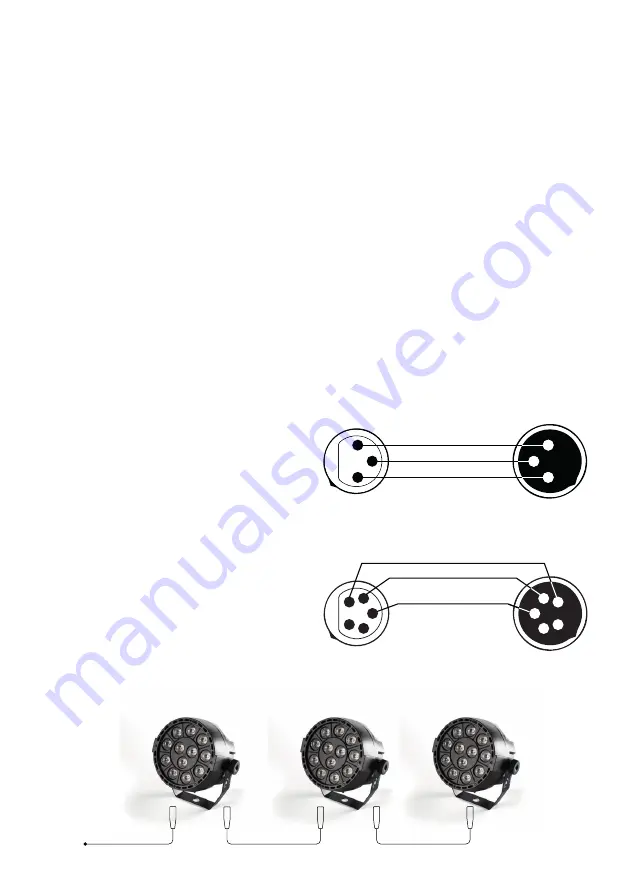
5.1 Connecting DMX signal

The  connection  is  performed  using  cable 

with XLR-female -> XLR-Male plugs.

4. INSTALLATION

5. CONNECTION

3. PRODUCT INFORMATION

weight. Also always use a safety cable that 

can hold 12 times of the weight of the unit 

when installing the fixture. The equipment 

must be fixed by professionals. And it must 

be fixed at a place where is out of the touch 

of people and has no one pass by or under 

it.

The  device  is  equipped  with  the  following 

interfaces:

1.   DMX (in/out): XLR 3(5)-pin socket

2.   Power (in/out): powerCON socket

1

3

2

2

FEMALE

XLR

GROUND

DMX +
DMX -

MALE

XLR

3

1

CAUTION!

  At  the  last  fixture,  the 

DMX signal has to be terminated with a 

terminator. Solder a 120Ω resistor between 

signal (-) and signal (+) into a XLR plug and 

plug it in the DMX output of the last fixture.

DMX

Controller

DMX 512

DMX 512

1

FEMALE

XLR

GROUND

DMX +

DMX -

MALE

XLR

2

3

4

5

1

2

3

4 5

3-pin XLR

5-pin XLR

Light source: 12pcs x 3W UV LEDs

Power supply: AC 100V/240V 50/60Hz, 

Power Consumption: 36W

Signal: DMX 512

 Housing: ABS

 3-Pin XLR DMX input/output

 Net Weight: 0,6kg

Dimensions: H(12)xW(12)xD(8,9) cm

Package: Carton Box

Summary of Contents for F7100328

Page 1: ...User Manual Instrukcja Obsługi F7100328 LED PAR 36 12xUV ...

Page 2: ...is higher than this Intheeventofseriousoperatingproblem stop using the fixture immediately Never try to repair the fixture by yourself Repairs carried out by unskilled people can lead to damage or malfunction Please contact the nearest authorized technical assistance center Always use the same type spare parts Do not connect the device to any dimmer pack Do not touch any wire during operation and ...

Page 3: ... be fixed by professionals And it must be fixed at a place where is out of the touch of people and has no one pass by or under it The device is equipped with the following interfaces 1 DMX in out XLR 3 5 pin socket 2 Power in out powerCON socket 1 3 2 2 FEMALE XLR GROUND DMX DMX MALE XLR 3 1 CAUTION At the last fixture the DMX signal has to be terminated with a terminator Solder a 120Ω resistor be...

Page 4: ...r or by a person with appropriate permissions Make sure that the power grid supply parameters are consistent with device parameters and limitations are not exceeded Using lamp the change rate of power voltage should be within 10 if the voltage is too high it will shorten the light s life if it s not enough the lamp will be dark Please restart it after turning off light for 20 minutes until full co...

Page 5: ... Press ENTER to turn the below value A3 01 A3 32 Adjust hopping speed slow to fast Sound Active Mode A4 01 A4 19 Press ENTER to turn the below value Select sound active program A4 01 A4 04 Adjust sound activated sensitivity Strobe Mode A5 01 A5 19 Press ENTER to turn the below value Select the LED position A5 01 A5 32 Adjust strobe speed slow to fast Static Color Dimmer r000 255 Adjust the brightn...

Page 6: ...onić głowę User Manual Instrukcja Obsługi CH Function Value Description 1 No Function 0 10 Static Color 11 50 CH2 to Select LED Position Auto Play 51 100 CH3 to Adjust Speed Fade 101 150 CH2 to Select LED Position CH3 to Adjust Speed Sound Active 151 200 Strobe 201 255 CH2 to Select LED Position CH3 to Adjust Speed 2 Different LED Position 0 255 3 Speed Adjustment 0 255 Slow to Fast 4 Dimmer for 5...

Page 7: ...ządzenie powinno być zainstalowane w dobrze wentylowanym pomieszczeniu w odległości co najmniej 15cm od najbliższej powierzchni ściany sufitu itp Jednocześnie należy upewnić się że otwory wentylacyjne nie są zatkane oraz wentylatory działają poprawnie Po wyjęciu urządzenia z opakowania należy sprawdzić czy nie zostało ono uszkodzone podczas transportu Przed podłączeniem do sieci elektrycznej należ...

Page 8: ...ię przy użyciu przewodu zakończonego z jednej strony wtyczką sieci elektrycznej i wtyczką typu powerCON z drugiej strony w zestawie Urządzenie musi być obsługiwane przez UWAGA W przypadku uszkodzenia przewodu nie należy dokonywać samodzielnejnaprawy Wymianalubnaprawamożebyćwykonanajedynie w serwisie producenta lub przez osobę z odpowiednimi uprawnieniami wykwalifikowany personel techniczny Należy ...

Page 9: ... slow to fast Fade Mode A3 01 A3 19 Press ENTER to turn the below value A3 01 A3 32 Adjust hopping speed slow to fast Sound Active Mode A4 01 A4 19 Press ENTER to turn the below value Select sound active program A4 01 A4 04 Adjust sound activated sensitivity Strobe Mode A5 01 A5 19 Press ENTER to turn the below value Select the LED position A5 01 A5 32 Adjust strobe speed slow to fast Static Color...

Page 10: ... 150 CH2 to Select LED Position CH3 to Adjust Speed Sound Active 151 200 Strobe 201 255 CH2 to Select LED Position CH3 to Adjust Speed 2 Different LED Position 0 255 3 Speed Adjustment 0 255 Slow to Fast 4 Dimmer for 5 7 CH 0 255 0 100 5 Position 1 0 255 6 Position 2 0 255 7 Position 3 0 255 8 Position 4 0 255 User Manual Instrukcja Obsługi ...

Page 11: ...LED PAR 36 12xUV Art No F7100328 ...

Page 12: ...www flash butrym pl F7100328 ...

Reviews: