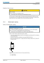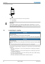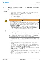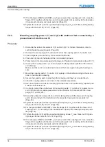
Assembling
5.2 Assembling the coupling
M3302-01en
Edition 09/2022
33
5.2.1
Mounting coupling parts 1 (1) and 2 (2) with shaft and hub connected by a
parallel key
5.2 Assembling the coupling
Procedure
1. Unscrew the set screw out of coupling parts 1 (1) and/or 2 (2) until it is no longer pos-
sible for there to be a collision with the parallel key or the shaft.
2. Clean the bores and shaft ends.
3. Coat the bores of coupling parts 1 (1) and/or 2 (2) and the shafts with MoS
2
assembly
paste (e.g. Microgleit LP 405).
4. Put coupling part 1 (1) or 2 (2) on the shaft.
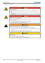
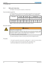
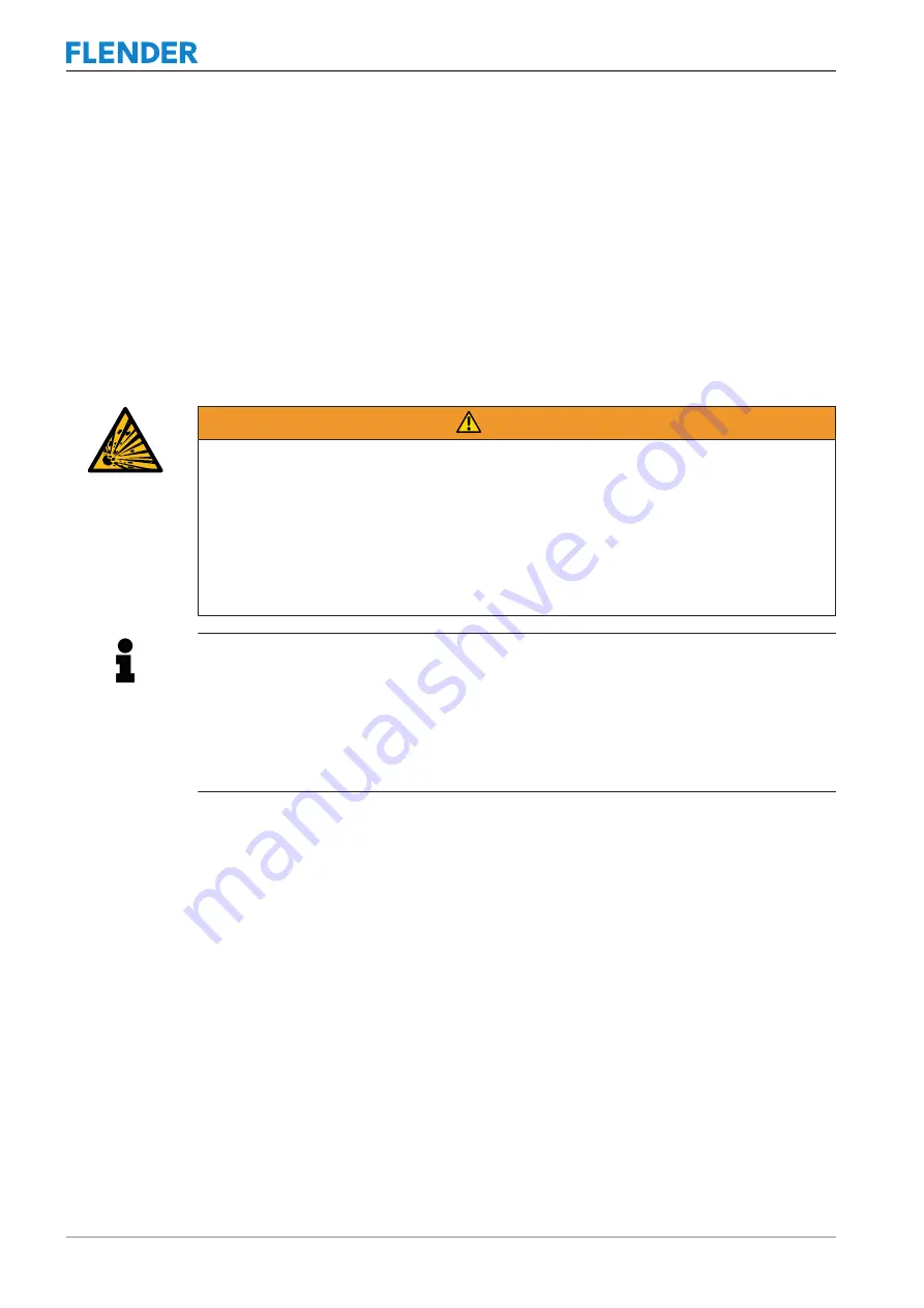
WARNING
Danger if the coupling fractures
If you do not observe the information stipulated here when assembling coupling parts with
conical bore, then this can cause the coupling to fracture in operation. There is a risk of
fatal injury from flying fragments. Bursting of the coupling can lead to an explosion in po-
tentially explosive atmospheres.
•
Mount the coupling part 1 (1) or 2 (2) with conical bore and parallel keyway on the
shaft in cold condition. Secure the coupling part with a suitable end plate without
pulling the coupling part further onto the cone (fitting dimension = 0).
Information
Coupling parts with cylindrical bore
To make assembly easier, you can heat coupling part 1 (1) or 2 (2) with cylindrical bore up
to a maximum of 120 °C if required. Note when doing this the temperature range of the rub-
ber disk element 5 (5) and/or 6 (6) (see Rubber disk elements 5 (5) and/or 6 (6)
(Page 77)). Remove the rubber disk element 5 (5) and/or 6 (6) if necessary. Protect adja-
cent components against damage and heating to temperatures above 80 °C.
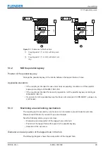
5. Secure the coupling part 1 (1) or 2 (2) with a set screw or an end plate. When securing
with a set screw the shaft must not protrude or be set back from the inner side of the
hub.
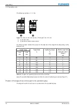
6. Tighten up the set screw or the screw to attach the end plate to the specified tightening
torque T
(for the set screw please refer to Machining an axial locking mechanism
7. If you have removed rubber disk element 5 (5) and/or 6 (6), screw the rubber disk ele-
ment 5 (5) and/or 6 (6) with the face end of coupling part 2 (2) according to the illustra-
tions in Spare parts drawing and spare parts list (Page 60).
8. Tighten the bolts (25) with the specified tightening torque T
A
torques for the bolts 25, 125, 31 (Page 76)).
9. For the types ESNW and ESDW, screw the flange (101) together with the face end of
10.Tighten the bolts (125) with the specified tightening torque T
A
(see Table A-25 Tighten-
ing torques for the bolts 25, 125, 31).
Summary of Contents for ELPEX-S
Page 6: ...Table of contents 6 Edition 09 2022 M3302 01en ...
Page 8: ...List of tables 8 Edition 09 2022 M3302 01en ...
Page 10: ...List of figures 10 Edition 09 2022 M3302 01en ...
Page 14: ...Introduction 1 4 Copyright 14 Edition 09 2022 M3302 01en ...
Page 22: ...Description 22 Edition 09 2022 M3302 01en Structure ...
Page 38: ...Assembling 5 3 Aligning the coupling 38 Edition 09 2022 M3302 01en ...
Page 40: ...Commissioning 40 Edition 09 2022 M3302 01en ...
Page 46: ...Operation 7 2 Fault causes and correction 46 Edition 09 2022 M3302 01en ...
Page 56: ...Service and support 9 1 Contact 56 Edition 09 2022 M3302 01en ...

