Assembling
5.2 Assembling the coupling
36
Edition 09/2022
M3302-01en
5.2.4.1
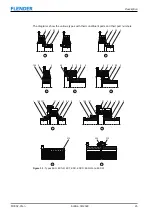
Mounting the one-part coupling part 3 (3)
5.2 Assembling the coupling
Procedure
1. Clean the coupling part 3 (3).
2. Flange-mount the coupling part 3 (3) on the mating part.
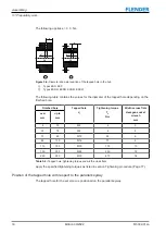
3. Tighten the bolts (25) with the specified tightening torque T
torques for the bolt connection of coupling part 3 (3) with the motor flywheel (Page 75)
or Table A-25 Tightening torques for the bolts 25, 125, 31 (Page 76)).
5.2.4.2
Mounting the two-part coupling part 3 (3)
5.2 Assembling the coupling
For sizes 680 and 770 of types ESD, ESDR and ESDW, the coupling part 3 (3) is a two-part
component. You can find an illustration of the designs in the drawings in Geometry data and
weights (Page 63).
Procedure
1. Clean the coupling part 3 (3).
2. Flange-mount the first half of coupling part 3 (3) to the mating part.
3. Tighten the bolts (25) with the specified tightening torque T
torques for the bolt connection of coupling part 3 (3) with the motor flywheel (Page 75)
or Table A-25 Tightening torques for the bolts 25, 125, 31 (Page 76)).
4. Apply a few drops of liquid screw locking agent (e.g. Loctite 243) to the screws (310).
Screw the two parts of coupling part 3 (3) with the bolts (310 and 310 or 320).
5. Tighten the bolts with the specified tightening torque T
A
torques for the bolts 310 (Page 76)).
5.3
Aligning the coupling
5.3 Aligning the coupling
5.3.1
Purpose of alignment
5.3 Aligning the coupling
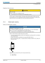
The shafts that are joined by the coupling are never on an ideal precise axis but have a cer-
tain amount of misalignment.
Misalignment in the coupling leads to restoring forces that can stress adjacent machine parts
(e.g. the bearings) to an unacceptable extent.
The misalignment values in operation result from the following:
• Misalignment due to assembly
Incorrect position due to a lack of precision when aligning
• Misalignment due to operation
Example: Load-related deformation, thermal expansion
You can minimise misalignment by aligning after assembly. A lower misalignment in the
coupling has the following advantages:
• Reduced wear of the elastomer components
Summary of Contents for ELPEX-S
Page 6: ...Table of contents 6 Edition 09 2022 M3302 01en ...
Page 8: ...List of tables 8 Edition 09 2022 M3302 01en ...
Page 10: ...List of figures 10 Edition 09 2022 M3302 01en ...
Page 14: ...Introduction 1 4 Copyright 14 Edition 09 2022 M3302 01en ...
Page 22: ...Description 22 Edition 09 2022 M3302 01en Structure ...
Page 38: ...Assembling 5 3 Aligning the coupling 38 Edition 09 2022 M3302 01en ...
Page 40: ...Commissioning 40 Edition 09 2022 M3302 01en ...
Page 46: ...Operation 7 2 Fault causes and correction 46 Edition 09 2022 M3302 01en ...
Page 56: ...Service and support 9 1 Contact 56 Edition 09 2022 M3302 01en ...


