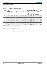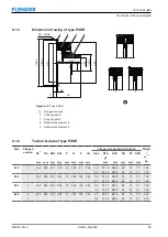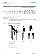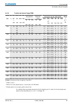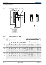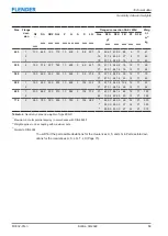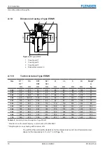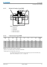
Technical data
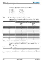
Shaft misalignment values during operation
74
Edition 09/2022
M3302-01en
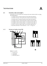
Comply with the clearances within the following limits during assembly:
A
min
= A - ΔS
A
max
= A + ΔS
S
min
= S - ΔS
S
max
= S + ΔS
LG
min
= LG - ΔS
LG
max
= LG + ΔS
T
min
= T - ΔS
T
max
= T + ΔS
LX
min
= LX - ΔS
LX
max
= LX + ΔS
A.2
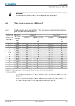
Shaft misalignment values during operation
Shaft misalignment values during operation
Maximum permissible shaft misalignments during operation ∆Kr
perm
and ∆Kw
perm
, stating the
values in mm (rounded).
Size
Permissible shaft misalignment ΔK
1500
at n = 1500 rpm
Radial
ΔKr
1500
mm
Angular
ΔKw
1500
degrees
220
1.2
0.5
265
1.2
0.5
290
1.2
0.5
320
1.2
0.5
360
1.2
0.5
420
1.3
0.4
465
1.3
0.4
520
1.4
0.4
560
1.4
0.4
580
1.5
0.3
680
1.5
0.3
770
1.5
0.3
Table A-9:
Maximum permissible shaft misalignment values during operation
The maximum permissible radial and angular misalignment depends on the operating speed.
Use the following formulae to calculate the maximum permissible misalignment in your sys-
tem:
ΔKr
perm
= ΔKr
1500
· FKV
ΔKw
perm
= ΔKw
1500
· FKV
Speed in rpm
500
1 000
1 500
3 000
Correction factor FKV
1.2
1.1
1.0
0.7
Table A-10:
Correction factor
Summary of Contents for ELPEX-S
Page 6: ...Table of contents 6 Edition 09 2022 M3302 01en ...
Page 8: ...List of tables 8 Edition 09 2022 M3302 01en ...
Page 10: ...List of figures 10 Edition 09 2022 M3302 01en ...
Page 14: ...Introduction 1 4 Copyright 14 Edition 09 2022 M3302 01en ...
Page 22: ...Description 22 Edition 09 2022 M3302 01en Structure ...
Page 38: ...Assembling 5 3 Aligning the coupling 38 Edition 09 2022 M3302 01en ...
Page 40: ...Commissioning 40 Edition 09 2022 M3302 01en ...
Page 46: ...Operation 7 2 Fault causes and correction 46 Edition 09 2022 M3302 01en ...
Page 56: ...Service and support 9 1 Contact 56 Edition 09 2022 M3302 01en ...

