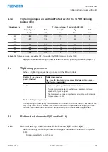
M3302-01en
Edition 09/2022
79
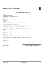
Declaration of Conformity
B
EU Declaration of Conformity
EU Declaration of Conformity
Product:
FLENDER ELPEX-S® couplings
Types ESD, ESDR, ESN, ESNR, ESNW, ESDW, EST
Name and address of the manufacturer:
Flender GmbH
Schlavenhorst 100
46395 Bocholt
Germany
This Declaration of Conformity is issued under the sole responsibility of the manufacturer.
This declaration refers to the product mentioned above.
The object of the declaration described above is in conformity with the relevant EU harmonisation legislation:
– Directive 2014/34/EU, Official Journal L 96, 29 March 2014, Pages 309-356
Harmonised standards or other technical specifications on which the Declaration of Conformity is based:
EN 1127-1
: 2019
EN 1127-2
: 2014
EN ISO 80079-36
: 2016
EN ISO 80079-37
: 2016
EN ISO/IEC 80079-38
: 2016
Notified Body, DEKRA Testing and Certification GmbH (0158) has received the technical documentation.
Signed for and on behalf of:
Flender GmbH
Bocholt, 2022-09-01
Dr Dennis Geers, President, Business Line Couplings
Summary of Contents for ELPEX-S
Page 6: ...Table of contents 6 Edition 09 2022 M3302 01en ...
Page 8: ...List of tables 8 Edition 09 2022 M3302 01en ...
Page 10: ...List of figures 10 Edition 09 2022 M3302 01en ...
Page 14: ...Introduction 1 4 Copyright 14 Edition 09 2022 M3302 01en ...
Page 22: ...Description 22 Edition 09 2022 M3302 01en Structure ...
Page 38: ...Assembling 5 3 Aligning the coupling 38 Edition 09 2022 M3302 01en ...
Page 40: ...Commissioning 40 Edition 09 2022 M3302 01en ...
Page 46: ...Operation 7 2 Fault causes and correction 46 Edition 09 2022 M3302 01en ...
Page 56: ...Service and support 9 1 Contact 56 Edition 09 2022 M3302 01en ...


