36
ZAPEX 3502 en
Operating instructions 10/2017
10.4
Demounting the coupling parts (1/2) in case of shaft-hub connection with parallel key
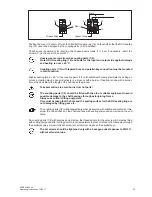
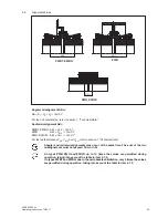
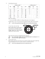
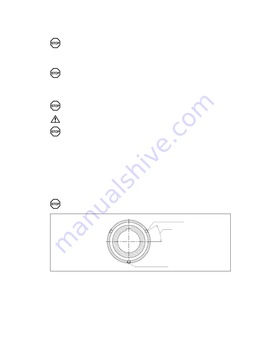
Unscrew the screw plugs (6) and drain off the oil or grease into a suitable vessel, as shown in the diagram
above (to simplify matters, in case of grease, add lightbodied oil to the used grease and mix).
All the oil or grease must be completely collected and disposed of in accordance with
the regulations applying.
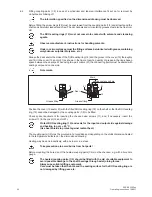
Undo the close-fitting bolt connection (8; 9) and the screw connection of the cover (11). Pull off the cover(s)
(10 and/or 21) and support them over the shafts. Move the coupled machines apart. Remove the flanged
sleeves (5) / coupling sleeve (5), the axialbacklash limiting device (52) and the brake disk (13).
Always use suitable lifting equipment!
Check the teeth, the seals (12) and the sealing surfaces for damage. Damaged parts must be replaced.
Remove set screw and/or axial retaining means. Mount suitable detaching device. Using a burner, heat
coupling part (to max. + 80 °C) along its length and above the parallel keyway.
Protect DUO sealing rings (12) and seals for the input and output side against damage
and heating to over + 80 °C.
Take precautions to avoid burns from hot parts!
Pull off coupling parts (1/2) smartly.
Always use suitable lifting equipment and detaching devices. The shaft bearings must
not be overloaded.
Care must be taken that the hole and the sealing surface for the DUO sealing ring are
not damaged by lifting gear, etc.
For refitting, the instructions in section 6, "Assembly", and section 7, "Startup", must be carefully
observed.
10.5
Demounting coupling parts (1/2) in case of cylindrical and tapered interference fit set up for hydraulic
shrinking off
The disassembly of the coupling must be carried out considering all precautions.
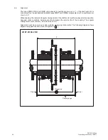
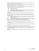
Unscrew-the screw plugs (6) and drain off the oil or grease into a suitable vessel, as shown in the diagram
(to simplify matters, in case of grease, add lightbodied oil to the used grease and mix).
All the oil or grease must be completely collected and disposed of in accordance with
the regulations applying.
Drainage hole
30°
Ventilation hole
Undo the close-fitting bolt connection (8; 9) and the screw connection of the cover (11). Pull off the cover(s)
(10 and/or 21) and support them over the shafts. Move the coupled machines apart. Remove the flanged
sleeves (5) / coupling sleeves (5), the axialbacklash limiting device (52) and the brake disk (13).
Summary of Contents for Zapex ZWB
Page 2: ......


