15
TRANSLATION OF THE ORIGINAL INSTRUCTIONS (Keep for future reference)
Document Code
Rev.
Date saved
Date printed
U300 INSTRUCTIONS
01
09/02/2016
09/02/2016
EN
*\*+#$'$*&%+*"&$#!)
?<$*#!"}%%<>%?##>>?$?!@<>#<##&%%?&%&#*$&%?!*<&>?&%?"#%"
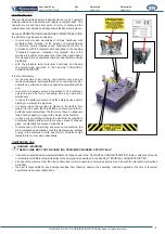
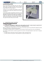
the pedal thus clamping them against the fence unit.
Movement of the rod clamp occurs at the same time as vertical clamping and is activated by a pneumatic actuator when the pedal is
pressed. For as long as the pedal is pressed, it clamps the mouldings for the entire duration of the nailing cycle.
?"%&%?<$*#!"!%'#<%<#$$<&%%?"%&&#*&%&#&<%?`%?!*<&%'&<
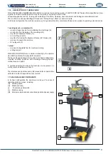
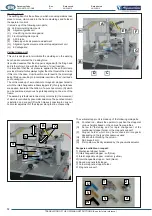
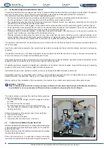
The front clamp is made up of:
;<#>
(H) Knob for securing the rod to the pneumatic actuator of the front clamp.
(I)
Holes for anchoring the cursor of the pneumatic actuator.
(L)
Front locking rod clamp
*%=#&]+*+*)*+#$
&&"!*<&;$<&!!&*&%?%?>&
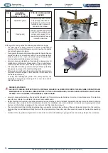
bench needs to be increased by installing the two side extensions
(A) and (B) (optional).
?;%&&#%%<%%?<%?!#$?&?\!%'
perfectly aligned with the working bench, see heading ASSEMBLY
OF SEPARATELY SHIPPED UNITS.
(A) Right
extension
(B) Left
extension.
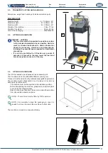
The machine is designed to be STATIC, i.e. it must be installed
&%?^#&$?<%%?^%?"#%%?'*<&
structure so that it remains stationary during operation.
If detached from the stand, the machine can be used on a horizontal,
sturdy and stable table.
The machine is LOADED AND UNLOADED MANUALLY:
I. MANUAL POSITIONING OF THE MOULDINGS to be
#!'*<&%?>&'&$?[>%?%?;<#<$*<
and locked
ii. MANUAL REMOVAL OF THE ASSEMBLED MOULDINGS from
%?>&'&$?[>%?%?;<#<$*<#&<*$<
^#&%=*]+"+<*%=#&+*))$"
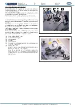
To extend the available work surface for the mouldings, it is possible
to install 6 brackets (C), 2 on each side, onto which a surface panel
in wood or other material (not supplied) is placed.
To install the brackets, please refer to the heading ASSEMBLY OF
SEPARATELY SHIPPED UNITS
(A)
90° bracket with slots and holes for fastening to the machine
and the wooden surface panel.
B
A
L
G
H
I
C

