24
TRANSLATION OF THE ORIGINAL INSTRUCTIONS (Keep for future reference)
Document Code
Rev.
Date saved
Date printed
U300 INSTRUCTIONS
01
09/02/2016
09/02/2016
EN
3.4.2. Compressed air supply
The compressed air supply must be maintained in compliance with the following technical prescriptions:
=
?$!"<#""*\!%'%?%\"#&<&%&%\"$<&%?%"#%?{"&!#%$<##!~;$@
pressure values are applied the components will be irreparably damaged.
=
%#&&%#$$&%%?#$%%?#%%?!#$?&]"&!#%$\%!$&%<##$!"&&%%?<%'%&&%>[&%?
context of protection against overpressure, a protection device must be installed coordinated with the machine’s pneumatic circuit, in
compliance with legislation and the legislative and regulatory provisions in force in the country of installation.
=
?"&!#%$\%!$!"<#""*\*&!%'%<%??%?"#$"@<<'\%?#&<!%'#<j#%*\
protected.
=
?$!"<#""*\*&!%?#@#$%&#&<$?##$%%$$"&<&%%?"$$#%&?>&&%?%"#
%?{"&!#%$<##!~"*&<&%$%&%%?"$<$#&#*%"@#*#&<%?!"#$$%
operation of the machine.
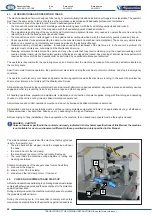
The following units are incorporated in the compressed air inlet point:
Standard supply:
$%$"*
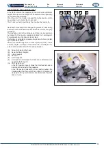
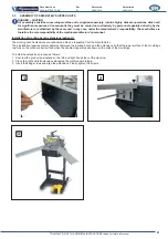
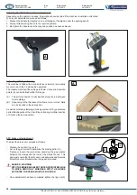
Pneumatic pedal hook-up
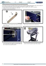
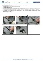
Before connecting the machine to the pneumatic system, you must
%$&&$%"%?$&%*"<#*
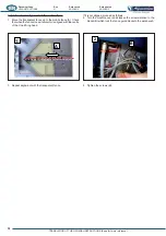
The three air lines which are connected to the pedal assembly must
be inserted in the three connectors located on the right-hand side
of the machine in the following order:
1) RED line in the connector on the outer side (1).
2) BLACK line in the intermediate connector (2).
3) TRANSPARENT line in the connector on the operator side
(3).
A
1
2
3
B

