36
TRANSLATION OF THE ORIGINAL INSTRUCTIONS (Keep for future reference)
Document Code
Rev.
Date saved
Date printed
U300 INSTRUCTIONS
01
09/02/2016
09/02/2016
EN
"x+[ #$)**++
?!#$?&%%<>%?#!'*&$&%>?$?!#&#**\
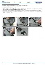
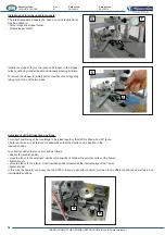
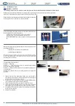
moved to reach the V-nail insertion positions.
The maximum stroke of the carriage is 80 mm. Various nail insertion
"&%$#&'<&<>%?&%?#&
?"$%?>&#*&%<#*&%?&'%>&
two mouldings.
(B)
Depending on the thickness of the frame, two or more V-Nails
can be inserted in the same point.
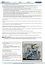
As well as moulding clamping, a braking system (AFC) guarantees
"$%'*$&#*%?&#*&&%<&!*%"*&%&
of V-nails in the same position.
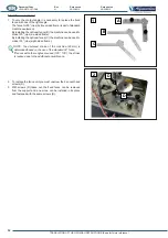
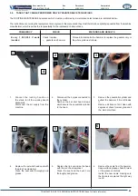
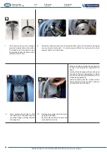
AFC brake unit adjustment
#<%%?'#&%["$<#**>+
- Slacken the central ring nut (2)
- Act on the grub screw to determine the braking action (1).
Tighten or loosen the grub screw observing the gap created
between the clamps and the rods of the mobile fences. This
gap must ensure that the fences move backwards and forwards
smoothly but are blocked when the pedal is pressed.
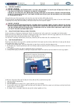
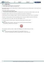
DANGER - WARNING
WITH THE BRAKE ENABLED THE FENCE MUST BE ABLE
TO MOVE SMOOTHLY WHEREAS WITH THE BRAKE
ACTIVATED THE FENCE MUST BE BLOCKED.
&$#<%!&%?#'&$!"*%<[%?%&%?&&%
"x+$*=<*%'+&*)*+#$
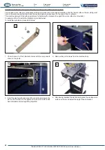
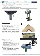
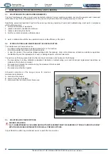
Depending on the operator’s needs, the workbench can be tilted if the machine is installed on its stand.
$#\%#<%!&%["$<#**>+
1. Slacken the handle (A) located on one of the legs of the stand, under the working bench.
2. Slowly tilt the working bench to the required position.
3. Re-tighten the handle once the required position has been achieved.
A
B
2
1
A

