37
TRANSLATION OF THE ORIGINAL INSTRUCTIONS (Keep for future reference)
Document Code
Rev.
Date saved
Date printed
U300 INSTRUCTIONS
01
09/02/2016
09/02/2016
EN
SUGGESTIONS FOR MAKING PERFECT JOINS
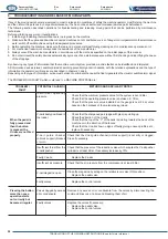
1) V-nail types
& < % & %?#% %? !#$?& $#& !# %" j#*%\ &
using a wide variety of materials, different V-nails are available
with different degrees of sharpness suitable for use with different
hardness values and characteristics of the materials being handled.
V-Nails can be divided up into the following categories:
V-nail type
!!
H3 3mm
(optional)
H5
5mm
H7 7mm
H10 10mm
H12
12mm
H15 15mm
It is advisable to carry out a check on the material in question for
selecting the most suitable sharpness.
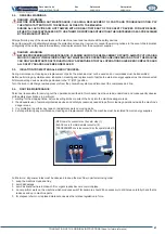
2) Stapling positions
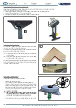
The following guidelines are designed to help you get the best
*%&%!j#*%\&+
-
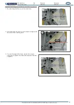
Avoid inserting V-nails close to the moulding edge. The minimum
recommended distance from the outer edge is at least 10mm.
?&$#%&#&>%?%& #*["%&%? #*&
the centre line of the frame.
\>?%&%! #*#$?&[%#<@#'*
to insert the outer V-Nail at 1/3 from the outer edge and the inner
V-Nail 1/4 from the inner edge.
%&%?@%$#*%""#?>&&%?
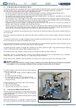
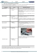
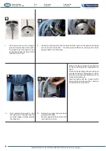
Rod clamp adjustment
?<$*#!"?##?*#<%%?"%&%?
rod clamp, proceed as follows:
*%%?<#&<!@%'#$>#<#&<>#<
- insert the rod on the relative drag screw located in the centre of
the guide channel (cursor).
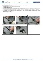
To correctly position the rod clamp, proceed as follows:
*%%?<!%#%'\#'%!!
!@%?<>#<&%*%#$?%?!*<&%'&<
- lower the punched rod so that the drag screw can be inserted
and allow for it to be locked in the new position.
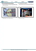
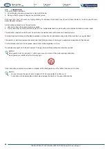
NOTES
In the case of prolonged use with the rod clamp, it is possible
to secure it to the cursor using countersunk screws.
L/2
1/3L
1/4L
L
L


