38
TRANSLATION OF THE ORIGINAL INSTRUCTIONS (Keep for future reference)
Document Code
Rev.
Date saved
Date printed
U300 INSTRUCTIONS
01
09/02/2016
09/02/2016
EN
4.5. WORKING
CYCLE
DANGER – CAUTION
During normal use, the machine must only process the products/materials indicated in this manual.
Safety measures and the indications on residual risks must always be observed during machine operation.
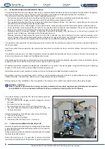
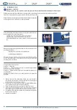
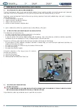
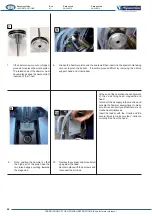
Insert the compressed air supply connector directly into the machine.
Check that the V-nail magazine is full and that the head corresponds
to the height of the V-nails and is correctly installed.
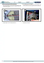
Connect the pedal and make sure the various pneumatic lines have
been inserted in the correct sequence.
1) RED line in the connector on the outer side (1).
2) BLACK line in the intermediate connector (2).
3) TRANSPARENT line in the connector on the operator side
(3).
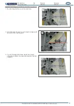
Make all the necessary regulations based on the dimensions of the
mouldings and then:
#<%&%?<$*#!"#&<!'*&$
@%$#*%""#<%!&%
?&@%?%>&'&$'&<[&%%?%!*<&
on the right-hand sside of the fence and then bring the left-hand
moulding (error condition).
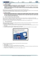
The pedal has three positions:
Position 1 - Stand-by
Position 2 - Pressed halfway down to automatically activate
horizontal and vertical clamping.
Position 3 – Pressed all the way down commands the hammer for
V-nail insertion.
Release the pedal for the new V-nailing position and repeat the
operation.
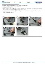
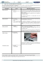
1. Taking care over the hazardous areas, use your hands to
accompany the movement of the fences and the mouldings up
to the desired V-nail insertion position.
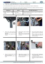
2. Position the rod clamp and then press the pedal halfway down
(2) to activate vertical and horizontal clamping.
3. Press the pedal (3) all the way down to insert the V-nail.
4. Lift the pedal to the halfway point (2) and then press all the way
down again (3) to insert the other V-nails in the same place.
5. Completely lift the pedal to release the moulding and reposition
the fences as required.
6. Repeat the operation
1
2
3
1
2
3


