background image

58

TRANSLATION OF THE ORIGINAL INSTRUCTIONS (Keep for future reference)

Document Code 

Rev. 

Date saved 

Date printed

U300 INSTRUCTIONS 

01 

09/02/2016 

09/02/2016

EN

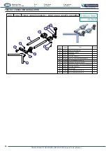
TABLE 23 - VERTICAL CLAMP UNIT 

 Alfamacchine
          10.2015

 U series      TAB.23     VERTICAL CLAMP GROUP - GRUPPO BLOCC. VERTICALE 

Numero

oggetto

Oggetto

Titolo

Quantità

401

753320010 POMELLO CON SPINTORE A MOLLA

1

402

334000100 ASTA BLOCC. VERTICALE PORTA TAMPONE

1

404

397100001 PAD  L-SHAPED 90 SHORE - BLACK

1

405

397100002 PAD  L-SHAPED 75 SHORE - YELLOW

1

406

397100003 PAD L-SHAPED 65 SHORE - BLUE

1

408

710100151 VITE  TCEI M10x25 UNI 5931 8.8 Z.B.

2

412

397100005 SUPPORTO ANGOLO INSERTO VULKOLLAN

1

413

244120130 PORTA TAMPONE

1

414

383600070 SUPPORTO CORTO ASTA BLOCCAGGIO VERTICALE

1

415

376400010 TRAVERSA

1

416

336210120 GRANO TRAVERSA M12

1

417

336100030 RONDELLA BLOCCAGGIO SUPPORTO BL.V.

1

418

244660010 MANIGLIA PER TRAVERSA M12

1

404

412

413

405

406

402

401

415

414

416

408

417

418

Summary of Contents for Alfamacchine U300

Page 1: ...L PLEASE RETAIN FOR FUTURE REFERENCE Name Function Model Type Serial number Year of construction Manual Revision FRAME ASSEMBLING MACHINE ASSEMBLY OF FRAMES BY INSERTION OF METAL V NAILS U300 previous version MINIGRAF 3 01 ...

Page 2: ... Product Name FRAME ASSEMBLING MACHINE Funzione Purpose ASSEMBLY OF WOODEN AND SYNTHETIC MDF MOULDINGS USING METAL V NAILS Modello Model Name U300 Tipo Type PNEUMATIC Numero di Serie Serial Number E CONFORME ALLE DISPOSIZIONI PREVISTE DALLE DIRETTIVE COMPLIES WITH THE FOLLOWING STANDARDS AND DIRECTIVES 2006 42 CE Direttiva Macchine Machinery Directive poiché rispetta tutti i requisiti essenziali d...

Page 3: ...IONING 20 3 2 LEVELLING THE MACHINE 20 3 3 ASSEMBLY OF SEPARATELY SHIPPED UNITS 21 4 INITIAL START UP AND USE OF THE MACHINE 25 4 1 WORKSTATIONS AND OPERATORS TASKS 26 4 3 CHECKS ADJUSTMENTS AND START UP 26 4 4 START UP 27 4 5 WORKING CYCLE 38 4 5 1 CYCLE STOP 39 5 MAINTENANCE TROUBLESHOOTING AND CLEANING 40 5 1 MAINTENANCE TECHNICIAN REQUIREMENTS 40 5 2 WORK STATIONS AND MAINTENANCE TECHNICIAN DU...

Page 4: ...NDATIONS PROVIDED IN THIS MANUAL NEVER TAMPER WITH IT FORCE IT OR USE IT INANYINAPPROPRIATE MANNER 1 INTRODUCTION TO USE 1 1 HOW TO CONSULT THIS MANUAL AND THE SYMBOLS ADOPTED Please pay particular attention to the words DANGER WARNING DANGER CAUTION and NOTE as used in this manual To draw the user s attention to certain information and provide warning messages the operations described in this man...

Page 5: ...ed improper and therefore strictly prohibited the dimensions specified in the heading TECHNICAL CHARACTERISTICS It is also compulsory received adequate training information concerning machine operations performance and any hazards associated with its use operating area before proceeding with any operations whatsoever starting to work with the machine where it is to be used that it is installed on ...

Page 6: ...andstill j as indicated in this manual outdoors or worksites with open windows and doors processing of materials and products that are not expressly indicated in the present manual processing of metal materials made of aluminium lightweight alloys and steel and its alloys DANGER CAUTION The manufacturer cannot be held liable for any faults caused by unreasonable improper and or incorrect use of th...

Page 7: ...g of at least IP54 0 C 32 F with electrical equipment protection rating lower than IP54 Ambient working temperature 5 C 41 F T 45 C 113 F Transport and storage temperature between 25 C 13 F and 55 C 131 F temperatures of up to 70 C 158 F are admissible for periods of less than 24 h Maximum altitude above sea level 1000m Minimum required light intensity 600 lux Relative humidity of 100 at 25 C 77 F...

Page 8: ...ds explosives j 1 4 TECHNICAL FEATURES Machine characteristics Work surface dimensions W x L 300x485mm 12 x19 Machine length 485mm 19 Machine width 300mm 12 1020mm 34 1 4 1340mm 53 Maximum machine height 450mm 18 Machine weight 32kg 70lbs V nail magazine capacity 220 pcs Max quantity of V nails inserted per position 9pcs V Nail insertion positions Multiple Max distance between V nails 80mm 3 1 4 C...

Page 9: ...ings of various hardness with multiple surface The main technical characteristics of the products handled by the machine described herein are provided below DESCRIPTION OF PRODUCTS HANDLED CHARACTERISTICS Minimum maximum width of moulding 6 60 mm 2 1 2 Minimum maximum thickness of moulding 6 80 mm 3 1 4 Weight 10 Kg 25 Kg Material Recommended sharpness Soft woods and plastic SW transparent stick M...

Page 10: ... due to the combustibility of the substances used in the machine and the products handled by the same To avoid the hazards resulting from the employer in addition to training and adequately informing the machine operator and maintenance technician on such risks must PPE to be used Protective gloves Safety footwear Safety clothing There is a residual risk for the maintenance technician when the saf...

Page 11: ... the instructions provided in this manual must never place What s more workers must never wear rings wrist watches personal accessories that may constitute a risk Make sure sleeves 1 9 DESCRIPTION OF SAFETY FUNCTIONS Protective devices installed on the machine DANGER WARNING IT IS STRICTLY PROHIBITED TO REMOVE THE SAFEGUARDS AND SAFETY DEVICES EXCEPT WHEN STRICTLY NECESSARY FOR THE PURPOSE OF CARR...

Page 12: ...l by authorized maintenance technicians maintenance technicians Irrespective of the circumstances dangerous openings in the machine safeguards they will not remain lodged in their locations in the absence of the fastening elements In sizing and selecting the guards and safety devices the possibility of access by persons aged 14 or over was used as a reference condition DANGER WARNING ACCESS TO ARE...

Page 13: ...effect or universal V nails 1 stand MACHINE FUNCTIONS are controlled manually by the operator who directly activates the pneumatic actuators mounted on stand optional with mouldings clamping system mobile fence and pedal If purchased without the stand the machine can be placed on a sturdy level and stable work bench The references and photos used in this manual refer to the machine with stand so t...

Page 14: ...or magnetic stopper holder to which the interchangeable rubber stoppers P of varying hardness are applied located at the bottom of a punched column N which can be positioned at various heights depending on the size of the frame The assembly is fastened to two sturdy columns S the movement of which is controlled by pneumatic actuators The punched column is installed on a support R which makes it po...

Page 15: ...ammer and their insertion into the overlying mouldings The magazine is in turn brought up against the L block support and by means of a V nail pusher supplies and aligns the V nails against the guide each time the hammer is activated The hammer is activated by a pneumatic cylinder which is controlled by the pneumatic pedal Perfect mechanical alignment of these parts ensures precise insertion singl...

Page 16: ...ator based on the size of the moulding in relation to the position of the front clamp rod clamp Fixed fences for 120 and 135 corners may also be installed in the fence support A for making frames with 6 and 8 sides respectively available as optional accessories AFC brake unit The AFC brake unit B is made up of a pneumatically activated device which comes into operation during the nailing cycle The...

Page 17: ...side extensions A and B optional perfectly aligned with the working bench see heading ASSEMBLY OF SEPARATELY SHIPPED UNITS A Right extension B Left extension The machine is designed to be STATIC i e it must be installed structure so that it remains stationary during operation If detached from the stand the machine can be used on a horizontal sturdy and stable table The machine is LOADED AND UNLOAD...

Page 18: ...0 at a temperature of 20 C 68 F 5 9 m s2 0 6G or higher 900 mbar or more Avoid places where there may be unexpected changes in temperature which could lead to the formation of condensate or freezing Storage temperature is construed as a short term value e g during transportation Condensation or freezing normally occurs in sites 2 2 CHECKS ON RECEPTION NOTES It is essential to check the packs at th...

Page 19: ...checked beforehand to obtain information about the necessary clearances and dimensions procedures _ 2 4 LIFTING AND HANDLING The U300 is divided up and delivered as an assembly kit j The machine must be transported in such a way as to avoid any damage to its components The machine must be transported in its installation position Before transporting the machine grease all non painted parts to avoid...

Page 20: ...port up to the time of delivery to the customer The machine is shipped packed in a special box and protected against damage by polystyrene inserts Maximum dimensions 660x440x500 AxBxC NOTE It is advisable to keep the packaging in case it is needed to store or transport the machine at a later date When storing the machine never stack two machines packed on a pallet with shrink wrap MULTIPLE TRANSPO...

Page 21: ...rce Seek advice from the delegated authorities and or the assistance of specialist companies authorised to dispose of pollutant or recyclable waste products DANGER CAUTION Warning pollution hazard do not dispose of the packing material in the environment retain it for future transport uses or consign it to a recycling company Evaluation and management of the packing materials in terms of biologica...

Page 22: ...rmal use of the machine and undue strain to the structure the machine must be stabilised during lifting operations The standard machine is supplied ready assembled on the stand which is secured to a pallet A Unscrew the 4 screws positioned under the pallet to remove the machine Install the 4 feet B using the relative wrench It is important to stabilize the stand by turning the threaded pin on each...

Page 23: ... These activities are therefore the sole responsibility of the machine manufacture s personnel The working bench extensions are optional and may be requested from the manufacturer Their installation requires precise alignment between the working bench and the extensions so that the lower surface of the mouldings rest fully on the entire support surface when the double stopper presses down on the e...

Page 24: ...support surface when the double stopper presses down on the ends of the mouldings An example of how to install the brackets is provided below To install the extensions proceed as follows 1 Check that each of the 6 brackets comes with the components shown in the photo 2 Remove the grub screws from the machine body 3 Insert the washer with spacer and the socket head screw in the slot on the bracket ...

Page 25: ...tand assembly Installation can be completed in a few simple steps as described below 2 Join the base to the uprights using the 4 screws provided caps 4 Add the cradle D by inserting the supports on the uprights 6 Position the machine on the cradle and fasten in place by inserting the three socket head screws E as indicated by the arrows 2 4 D 5 6 E 3 1 A B C ...

Page 26: ...umatic circuit in compliance with legislation and the legislative and regulatory provisions in force in the country of installation j protected operation of the machine The following units are incorporated in the compressed air inlet point Standard supply Pneumatic pedal hook up Before connecting the machine to the pneumatic system you must The three air lines which are connected to the pedal asse...

Page 27: ...on device as can be seen in the pneumatic diagram supplied with the machine is supplied for the sole source normal conditions of use PNEUMATIC SUPPLY ISOLATOR DEVICE The unit is located outside the machine s base 4 INITIAL START UP AND USE OF THE MACHINE DANGER WARNING THE MACHINE MUST ONLY BE OPERATED BY AUTHORISED AND DULY TRAINED PERSONNEL WITH ADEQUATE TECHNICAL EXPERIENCE MACHINE OPERATORS MU...

Page 28: ...ing operations while the machine is running In the event of a problem he she must not intervene but simply call the Maintenance Service All operations performed by the operator must be carried out with all protection devices activated all guards in place and all safety devices checks must be carried out by trained skilled maintenance personnel All maintenance and control operations must be carried...

Page 29: ...ght hand side of the machine in the following order 1 RED line in the connector on the outer side 1 2 BLACK line in the intermediate connector 2 3 TRANSPARENT line in the connector on the operator side 3 Insert the V nails as follows A Turn the PLV valve 1 lever to the OFF position B the V nail pusher cylinder is opened C Insert the stick of V nails in the magazine 2 ensuring that the sharp part g...

Page 30: ...follows 2 Lift the head upwards and out 3 Move the V nail pusher back using the relative control lever on the right hand side of the machine s workbench to access the magazine 4 Insert the new V nails of the required height in the magazine and move the V nail pusher forward by activating the control lever 5 Insert the new head of the height matching the V nails taking care to check that the number...

Page 31: ...ome into contact then tighten the socket head screws 5 Without forcing it move the magazine up against the hammer after having loosened the two M5 screws locking the magazine in place 6 Check that the coupling between the V nail magazine and hammer is perfect 7 Tighten the M5 screws which lock the magazine in place 8 Insert a V nail in the magazine move it up against the L block support to check t...

Page 32: ...Move the transparent fence up to the mobile fence A Check that when the fence moves its bisector is aligned with the centre If it is not aligned proceed as follows 2 Turn the machine over and slacken the screws relative to the blocks B which lock the fence guide blocks to the workbench 3 Repeat alignment with the transparent fence 4 Tighten the screws B 1 A B 2 ...

Page 33: ...ument Code Rev Date saved Date printed U300 INSTRUCTIONS 01 09 02 2016 09 02 2016 EN x 1 Move the transparent fence up to the mobile fence 2 Check that when the fence moves its bisector is aligned with 3 To correct the angle of the fences slacken the 4 screws completed 3 2 1 ...

Page 34: ...e machine can be used to By installing the optional fence C the machine can be used to NOTE the declared stroke of the machine 80mm is determined based on the use of the standard 90 fence If fences with other angles are used 120 135 the stroke is reduced due to the additional encumbrance 2 To replace the fence unit you must unscrew the 2 socket head screws D from the support and a new one can be i...

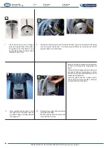
Page 35: ...he magnetic one you must unscrew the screw H which secures it to the rod and pull it downwards and out 1 To adapt the position of the stopper A to the thickness of the frame proceed as follows a Pull the click knob out b Lift or lower the punched rod based on requirements c Release the click knob to block the column 3 Fasten the magnetic support D or the single stopper holder B to the rod clamp by...

Page 36: ...itioning it under the slot and manually pressing it in place To remove the stopper A simply pull it out with your hand by gently taking hold of one of the two sides Adjustment of V nail insertion positions The fence can be moved forward or backwards so that the V nails can be inserted in the required position To correctly position the fence proceed as follows In this way the operator can easily us...

Page 37: ...r the work pressure proceed as follows 1 Lift the knob by about 3 4mm 2 Turn it clockwise to increase the pressure or anticlockwise to reduce the pressure 3 Press the knob to lock it back in place The following operating pressure values are recommended Hardness Air Pressure Soft Wood 2 bar 30 psi 4 bar 58 psi Medium Hard Wood 4 bar 58 psi 6 bar 87 psi Very Hard Wood 6 bar 87 psi 8 bar 115 psi Pres...

Page 38: ... the grub screw to determine the braking action 1 Tighten or loosen the grub screw observing the gap created between the clamps and the rods of the mobile fences This gap must ensure that the fences move backwards and forwards smoothly but are blocked when the pedal is pressed DANGER WARNING WITH THE BRAKE ENABLED THE FENCE MUST BEABLE TO MOVE SMOOTHLY WHEREAS WITH THE BRAKE ACTIVATED THE FENCE MU...

Page 39: ...ting the most suitable sharpness 2 Stapling positions The following guidelines are designed to help you get the best j Avoid inserting V nails close to the moulding edge The minimum recommended distance from the outer edge is at least 10mm the centre line of the frame to insert the outer V Nail at 1 3 from the outer edge and the inner V Nail 1 4 from the inner edge Rod clamp adjustment rod clamp p...

Page 40: ...ake all the necessary regulations based on the dimensions of the mouldings and then on the right hand sside of the fence and then bring the left hand moulding error condition The pedal has three positions Position 1 Stand by Position 2 Pressed halfway down to automatically activate horizontal and vertical clamping Position 3 Pressed all the way down commands the hammer for V nail insertion Release...

Page 41: ...Date printed U300 INSTRUCTIONS 01 09 02 2016 09 02 2016 EN 4 5 1 CYCLE STOP DANGER WARNING THE MACHINE MUST BE SWITCHED OFF AFTER USE THE COMPRESSED AIR LINE MUST BE DISCONNECTED PNEUMATICACTUATORS MAY HOLDACCUMULATED ENERGY WHICH MUST BE DISCHARGED OF PRESSURE TOAVOID HAZARDOUS UNEXPECTED MOVEMENTS ...

Page 42: ...ce technician duties are troubleshooting and the replacements of worn or damaged parts or structural elements The work zones that may present risks for the machine s maintenance technician are the following indicated in this instruction manual 5 3 MAINTENANCE PRESCRIPTIONS DANGER WARNING ALL THE MAINTENANCE CLEANING AND PARTS REPLACEMENT MUST BE CARRIED OUT SOLELY AND EXCLUSIVELY WITH THE MACHINE ...

Page 43: ...ance cleaning and replacement of parts the machine must not be used and no commands must be transmitted Before performing any maintenance lubrication cleaning and replacement of parts etc external energy supplies must be disconnected All disconnecting devices must be padlocked in the 0 OFF position Turn the knob to discharge residue pressure from the pneumatic system and disconnect the compressed ...

Page 44: ... provide equivalent quality and safety Check their integrity both internally and externally and make sure there are no signs of wear or breakage For any type of intervention or to replace parts call in the maintenance service During operation it is possible that V nails come out of the magazine and remain in circulation near the nailing head Remove them using the magnetic pen provided If they beco...

Page 45: ...00 V nails inserted CHECK Check replace 1 Slacken the locking handle on the stand to tilt the working bench backwards Disconnect the air supply from the machine 2 Disconnect the 2 pipes connected to the cylinder Remove the 4 socket head screws which secure the pneumatic cylinder to the head 3 Remove the pneumatic cylinder and extract the hammer if it is still inside it Remove all traces of dirt cl...

Page 46: ...n the special hole taking support head and V nail loader 9 Note position the hammer so that the high part of the piston has the two raised edges pointing towards the magazine 10 Replace the cylinder and move it well up against the head Secure in place with the 4 screws and reconnect the air lines At the end of the operation check alignment of the V nail firing head magazine and head reconnect the ...

Page 47: ...sture to keep said areas of the machine in a suitable operating condition Use suitable tools and equipment to check the tightness of terminals screws nuts bolts and connections in general on both the equipment and the machine The necessary inspections concern in the safety function it is designed to perform for example a reduction in resistance to impact caused by scratches damage to Plexiglas pan...

Page 48: ...f simple personal protective equipment Cleaning operations of the internal parts of the machine must be performed by the maintenance service operations should be carried out by the same personnel who usually work on the machinery rather than personnel from a cleaning company who may not observe all the recommendations indicated herein All cleaning operations must be carried out only after the mach...

Page 49: ... type of operation being carried out and depending on the substances used for cleaning Comply with the methods of use and use all the necessary PERSONAL PROTECTIVE EQUIPMENT SPECIFIED BY THE SUPPLIER OF SUCH SUBSTANCES detergent on non metal parts which when necessary can be cleaned using a neutral non foaming water based detergent ONLY If necessary metal parts can be cleaned using a lint free clo...

Page 50: ...ded with each individual lubrication product used The lubrication operations which must be performed by maintenance technicians are indicated below To obtain high performance and faultless operation it is important to lubricate moving parts of the machine on a regular basis The position of machine components which need lubricating is shown in the layout provided as an appendix to this manual For t...

Page 51: ...016 EN FREQUENCY At least once every six months Every 200 service hours LUBRICATION Maintenance technician Hammer piston METHODS AND RESULTS Lubricate the hammer piston by following the instructions provided in the heading ROUTINE MAINTENANCE Lubricate the carriage guides located under the working bench Automatic lubrication of the pneumatic actuators ...

Page 52: ...lly pressed and then the button is pressed the properly w more than once operation starts out correctly but w Insufficient operating pressure V nails badly positioned in the loader V nail guide channel L block support blocked or worn V nails pusher Faulty V nails V nail magazine open Faulty valves Valves clogged by excess oil or condensate Faulty valves METHODS AND ANCILLARY NOTES Check that the m...

Page 53: ...hammer Obstructed hammer not at the same level as the working bench Check that the AFC braking system is working properly Balancing cylinder powered Machine moving parts are not well lubricated METHODS AND ANCILLARY NOTES Remove oil and or condensate Replace the pedal valve Replace the faulty control valves Change the V nails for suitable ones Check and if necessary correct the position of the ver...

Page 54: ... RENDERED INOPERATIVE AND FREE FROM ALL POTENTIAL HAZARDS Decommissioning of the machine must be carried out by specialised and suitably equipped personnel If the client does not have the right personnel or tools to be able to proceed with demolition of the machine in total safety and in such a way as to safeguard the operators involved he must seek the assistance of the machine manufacturer s tec...

Page 55: ...at all plastics metal materials and electrical components which must be disposed of separately are duly sorted The employer must be aware of all the statutory legislation in force in the country of disposal and must operate in compliance with the relative provisions It is prohibited to dump the machine in environment All violations are punishable by law IDENTIFICATION DATA MANUFACTURER ALFAMACCHIN...

Page 56: ...1 30 M3 METAL FRAME CARCASSA M3 291690010 1 31 VERTICAL CLAMP CYLINDER CILINDRO BLOCCAGGIO VERTICALE 225220010 2 32 TAB 23 VERTICAL CLAMP GROUP ASSEMBLY GRUPPO BLOCCAGGIO VERTICALE M3 1 33 TAB 22A AFC BRAKE ASSEMBLY MONTAGGIO GRUPPO FRENO AFC 1 34 TAB 21 M3 FENCES GROUP ASSEMBLY MONTAGGIO GRUPPO SQUADRA M3 1 35 TAB 20 HEAD GROUP ASSEMBLY MONTAGGIO GRUPPO TESTA 1 36 TAB 24 CE SAFETY GUARD PROTECTIO...

Page 57: ...OR 6237 Di59 69 CORDA 5 34 NBR70 1 268 720250004 OR DI 64 77 CORDA 2 62 1 269 710100105 VITE TCEI M6x25 UNI 5931 8 8 Z B 2 272 722260014 GUARNIZIONE A LABBRO M5 7060 1 290 710100070 VITE TCEI M6x8 UNI 5931 12 9 5 291 394950030 TESTINA H10 1 292 394950050 TESTINA H15 1 293 394950040 TESTINA H12 1 294 394950020 TESTINA H7 1 295 394950060 TESTINA H5 1 300 710100066 VITE TCEI M6x80 UNI 5931 8 8 Z B 4 ...

Page 58: ...LO MASCHIO M6x25 1 435 336100020 RONDELLA MORSETTO 1 480 375200010 SQUADRA 90 1 481 383900020 SUPPORTO GUIDA ASTE 1 482 243150010 MORSETTO FINECORSA SQUADRA MOBILE 2 483 710100046 VITE TCEI M5x18 UNI 5931 8 8 Z B 4 484 718250005 RONDELLA PIANA 5x20 UNI 6593 Z B 4 485 393150010 MORSETTO BLOCCAGGIO ASTE SQUADRA M3 A2M 1 486 383900010 SUPPORTO GUIDA ASTA 2 487 334000020 ASTA SQUADRE 2 488 710100073 V...

Page 59: ...RONDELLA PER FRENO M3 GRANDE 1 474 225170010 COMPLESSIVO FRENO M3 1 475 336300010 POMELLO FRENO M3 1 476 714300042 GRANO STEI 12x16 UNI 5923 12 9 PASSO 1 25 1 476 475 474 473 472 471 416 Numero oggetto Oggetto Titolo Quantità 458 384800010 PIATTO ASTA FOGLIA M3 1 459 391950010 CORPO FOGLIA M3 M4 1 460 710200041 VITE TSPEI 5x10 UNI 5933 10 9 Z B 2 U300 TAB 22A AFC BRAKE SYSTEM FRENO AFC 458 459 460...

Page 60: ...100 ASTA BLOCC VERTICALE PORTA TAMPONE 1 404 397100001 PAD L SHAPED 90 SHORE BLACK 1 405 397100002 PAD L SHAPED 75 SHORE YELLOW 1 406 397100003 PAD L SHAPED 65 SHORE BLUE 1 408 710100151 VITE TCEI M10x25 UNI 5931 8 8 Z B 2 412 397100005 SUPPORTO ANGOLO INSERTO VULKOLLAN 1 413 244120130 PORTA TAMPONE 1 414 383600070 SUPPORTO CORTO ASTA BLOCCAGGIO VERTICALE 1 415 376400010 TRAVERSA 1 416 336210120 G...

Page 61: ...0100047 VITE TCEI M5x20 UNI 5931 8 8 Z B 1 429 381300180 SUPPORTO DX PROTEZIONE CE 1 430 381300170 SUPPORTO FISSO DX PROTEZIONE CE 1 431 388200020 SUPPORTO VALVOLA PROTEZIONE 1 Numero oggetto Oggetto Titolo Quantità 432 710200055 VITE TSPEI 5x16 UNI 5933 10 9 ZB 1 433 732540003 MICROVALVOLA 0ALF106 A 1 434 753320004 POMELLO MASCHIO M6x25 2 435 336100020 RONDELLA MORSETTO 2 436 710100203 VITE TCEI ...

Page 62: ...ALFAMACCHINE S r l Via Selva 23 25 47122 Forlì FC Tel 39 0543 783301 Fax 39 0543 783302 http www alfamacchine com ...

Reviews: