11
TRANSLATION OF THE ORIGINAL INSTRUCTIONS (Keep for future reference)
Document Code
Rev.
Date saved
Date printed
U400 INSTRUCTIONS
01
02/10/2015
02/10/2015
EN
1.10. DESCRIPTION OF THE MACHINE
|} | #!#$?&"<$&><&#!"$$#**\%&%%?%?#!
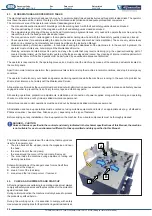
mouldings (which maybe pre-glued or dry) using metal V-nails.
All operating phases such as: loading and unloading of the frame, clamping, head movement and nailing are completely manual.
The machine can use special Alfagraf V-nails with “Pulling Power” effect or standard V-nails.
&%'#$$&#%&%?!#$?&!#<"#<%*%$%[$!"*%>%?'##&<#"#%&&%#&<`&+
<*%+'+&?&*!)$<@
=
#&*%""<@$!!'*`&%?!*<&[
=
#<@$&%$*#!"&%?!*<&
=
#\%!#*&!&%&$[
=
#&#*!##`&[
=
#&#*&%&\%!>?$?#"&!#%$#$%#%[
=
#"&!#%$#$%#%
1 stand
=
#%#\>%?*<%&#$$
=
##<%#'*%!#$?&*@**&
MACHINE FUNCTIONS are controlled manually by the operator
who directly activates the pneumatic actuators.
?#*&<?>%?!#$?&&%'#$$&#%&[
complete with lever with manually activated button, mouldings
clamping system, mobile fence and pedal.
If purchased without the stand, the machine can be placed on a
sturdy, level and stable work bench.
The references and photos used in this manual refer to the machine
with stand so that all aspects are fully covered.
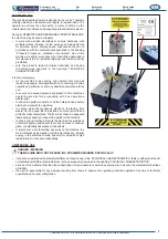
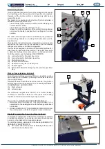
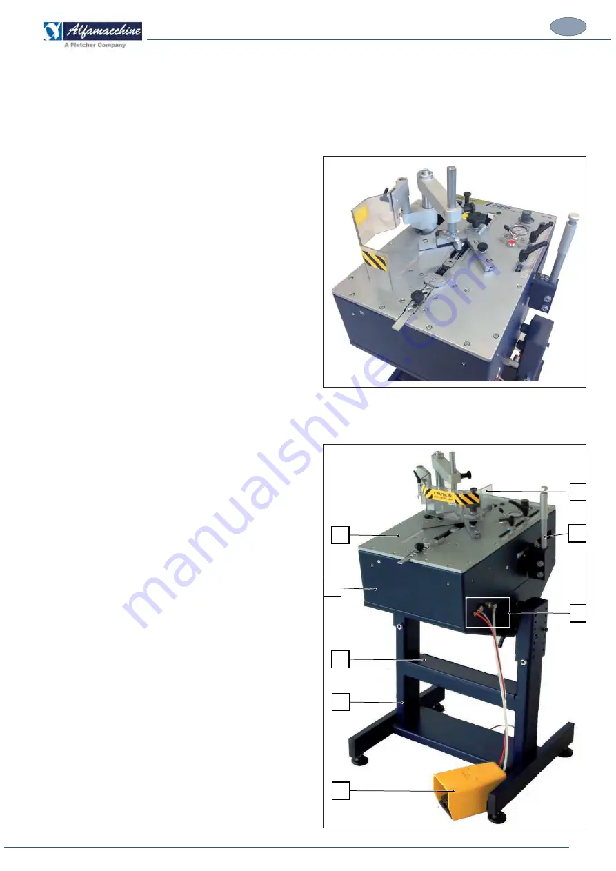
1.11. MAIN MACHINE COMPONENTS
& % '#$ $&#%& %? !#$?& !#< " #
operating units and zones, including:
(A) Working
bench
(B) Accessories compartment door
(C) Stand
(D) Pneumatic pedal switch
(E) Machine casing
(F) External compressed air connections, pedal and power supply
(G) EC
safeguard
(H) Handle for moving head and controls
F
A
B
C
D
H
E
G


