14
TRANSLATION OF THE ORIGINAL INSTRUCTIONS (Keep for future reference)
Document Code
Rev.
Date saved
Date printed
U400 INSTRUCTIONS
01
02/10/2015
02/10/2015
EN
"^#'$$+=+&+
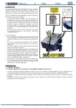
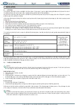
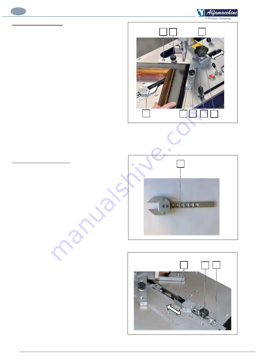
The fence unit, positioned on the working bench, can slide along
%?#!'*\*&%?&&%%"%&#<%<'\%?
operator based on the size of the moulding in relation to the position
of the front clamp (rod clamp).
The knob (C) locks the fence unit onto the working bench by means
of the clamp (E).
Once locked in place, the fence provides a stable stop guide for
$#%&%?$&%'&<
?%>!'*"#%&%#**<&*\&%?;<&$[
#%%<>%?#&'%?#%%?\$#&'%*%<&*#%&%%?
>&'&$?%?#%%?\%%?"*%?#!!*<&
better.
Fixed fences for 120° and 135° corners may also be installed in
the clamp (E) for making frames with 6 and 8 sides respectively
#@#*#'*#"%&#*#$$?%>;<&$<&%
have mobile parts (A).
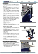
The tilting fence unit with a 90° angle, for frames with 4 sides,
installed as standard equipment, is made up of the following main
elements:
*%&<%">%?#<%#'*%*%
&'#<%&%?%*%
(C) Knob for locking the fence unit.
(D) Fixed fence with 90° corner, interchangeable.
(E) Locking
clamp.
*]*+#$'$*&%+*"&$#!)
?<$*#!"}%%<>%?%>!'*#>>?$?#!@<
forward against the internal corner of the mouldings when the
operator presses the pedal thus blocking them against the fence unit.
Movement of the rod clamp is provided by a pneumatic actuator
and, as long as the pedal is pressed, it keeps the mouldings locked
in place for the entire V-nailing cycle, even when the vertical clamp
*#<%#**>!@!&%%?&&%#&<%?&%&
&#*&@#"%&#*&%?&*&
Usually the position of the rod clamp is always kept the same
>?#%@%?`%?!*<&'&&<%%?&$&%
>?$?#<%<
The front clamp is made up of:
'*#>
(H) Knob for securing the rod to the pneumatic actuator of the
front clamp.
(I)
Holes for anchoring the cursor of the pneumatic actuator.
(L)
Front locking rod clamp
A B
C
F
A B
D E
G
H
I
L

