15
TRANSLATION OF THE ORIGINAL INSTRUCTIONS (Keep for future reference)
Document Code
Rev.
Date saved
Date printed
U400 INSTRUCTIONS
01
02/10/2015
02/10/2015
EN
#"!*;+#+"$
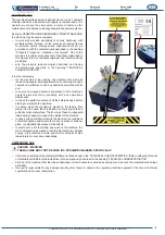
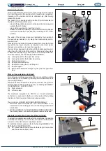
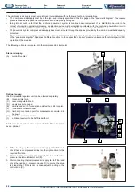
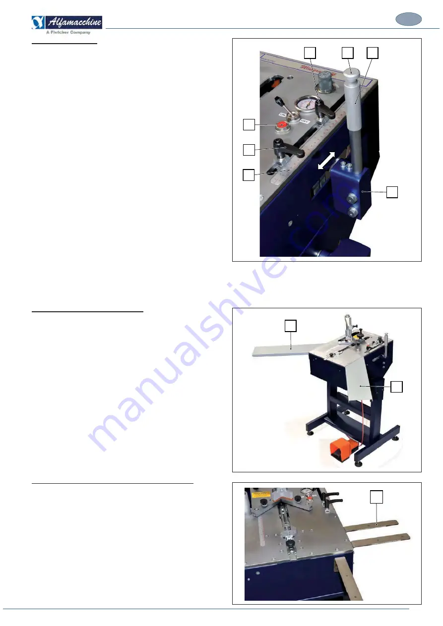
This device allows the operator to move the carriage which supports
%?&#*&&%%%?"&%&>?$?&#*#%'&%<
Operation of the handle controls is obtained only after having
pressed the pedal.
The handle (E) is equipped with a button (D) which activates a
double-command pneumatic valve:
-
press half way (light pressure) to activate vertical clamping and
#$%@#%%?'#
"#**%?>#\<>&%&%%?&#*
-
release the button completely to lift the vertical clamping stopper
#&<!@%??#&<*%"%&%?&#*&&%&#&>
position.
The ends of the carriage stroke are delimited by the position of
the two locking handles (A, B) along the double scale (metric,
imperial) ruler.
Pressing of the red button (G) makes it possible to move the handle
beyond the top travel stop (A), as required in the V-nail loader
changeover operation or to clean the magazine.
The machine is designed to function with the handle positioned on
%?%?*%?%<%?!#$?&%%#%#>%"
to dismantle the support (F) and position it on the opposite side.
For further details, see the heading ADJUSTMENTS.
(A)
Locking handle for the upper travel stop.
(B)
Locking handle for the bottom travel stop.
(C) Metric/imperial
ruler
(D) Double command button
|#&<*!@&%?&#*&&%
(F) Handle
support
(G) Button which allows the carriage to go beyond the upper travel
stop.
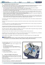
*%=#&_+*+*)*+#$
&&"!*<&;$<&!!&*&%?%?>&
bench needs to be increased by installing the two side extensions
(A) and (B) (optional).
?;%&&#%%<%%?<%?!#$?&?\!%'
perfectly aligned with the working bench, see heading ASSEMBLY
OF SEPARATELY SHIPPED UNITS.
(A) Right
extension
(B) Left
extension.
The machine is designed to be STATIC, i.e. it must be installed
&%?^#&$?<%%?^%?"#%%?'*<&
structure so that it remains stationary during operation.
The machine is LOADED AND UNLOADED MANUALLY:
I. MANUAL POSITIONING OF THE MOULDINGS to be
#!'*<&%?>&'&$?[>%?%?;<#<$*<
and locked
ii. MANUAL REMOVAL OF THE ASSEMBLED MOULDINGS from
%?>&'&$?[>%?%?;<#<$*<#&<*$<
`#&%=*_+"+<*%=#&*)*+#$
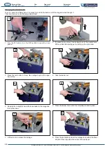
To extend the available work surface for the mouldings, it is possible
to install 6 brackets (A), 2 on each side, onto which a surface panel
in wood or other material (not supplied) is placed.
To install the brackets, please refer to the heading ASSEMBLY OF
SEPARATELY SHIPPED UNITS
(A)
90° bracket with slots and holes for fastening to the machine
and the wooden surface panel.
A
D
E
G
B
C
F
B
A
A

