33
TRANSLATION OF THE ORIGINAL INSTRUCTIONS (Keep for future reference)
Document Code
Rev.
Date saved
Date printed
U400 INSTRUCTIONS
01
02/10/2015
02/10/2015
EN
+#$$#*+*=+&#+#'$*))
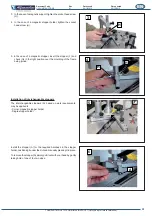
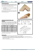
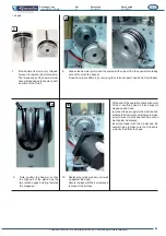
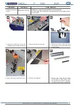
The interchangeable stoppers (A), based on work requirements,
may be applied to:
&!#&%$%""?*<
- Single stopper holder
Install the stopper (A) for the required hardness in the stopper
holder, positioning it under the slot and manually pressing it in place.
To remove the stopper (A) simply pull it out with your hand by gently
taking hold of one of the two sides.
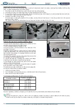
3. In the case of a magnetic support, tighten the socket head screw
(H).
4. In the case of a magnetic stopper holder, tighten the socket
head screw (H).
5. In the case of a magnetic stopper, insert the stopper (F) and
check it is in the right position over the moulding of the frame
'&&<
3
H
5
F
6
A
4
H
H


