37
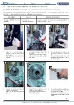
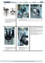
TRANSLATION OF THE ORIGINAL INSTRUCTIONS (Keep for future reference)
Document Code
Rev.
Date saved
Date printed
U400 INSTRUCTIONS
01
02/10/2015
02/10/2015
EN
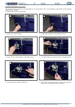
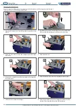
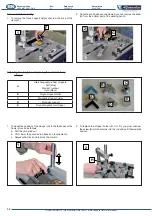
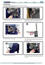
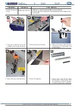
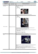
3. Extract the handle from the machine.
4. The dismantled handle appears as in the photo with the three
pipes, black, white and red, connected to the pneumatic valve
activated by the button.
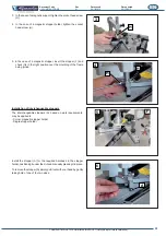
5. Position the handle on the other side.
6. Secure the handle to the carriage with the 2 screws and
reconnect the three pipes in the exact same position as they
were before.
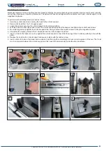
1. Remove the 2 screws securing the lever to the carriage.
2. Extract the 3 pipes from the connectors, taking care to make a
note of the exact position of each one (black, white, red).
Position of the handle
The machine is designed to operate with the handle on either the right or left side.
To change its position proceed as follows:
3
4
5
6
1
2

